background image

Removing the Table Tops

EMC 6/4, 6/4M, 6/4MT, EMC 10/4, EMC 10/4T:

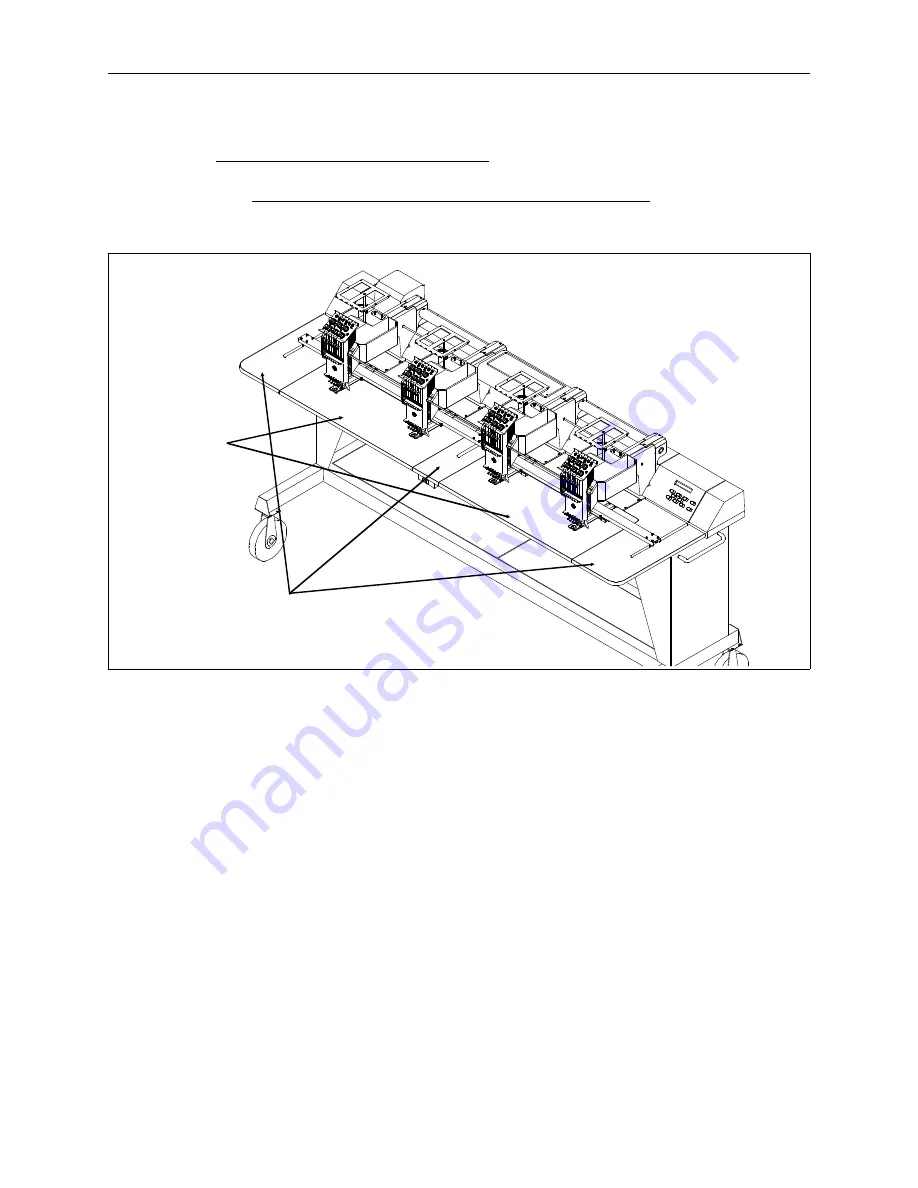
Remove the table top inserts in the order shown in Figure 1-4.

Use a small brush or can of compressed air to clean any dust or accumulated
lint from underneath the table tops themselves. Look for any foreign objects
(scissors, pens, needles, etc.) that may have fallen inside the channels.

Remove these
sections first

Remove these
sections second

Figure 1-4

1-6

Exterior Surfaces

Basic Maintenance

Melco Embroidery Systems

Summary of Contents for Melco Advantage 18

Page 1: ...ing Peripherals A Company of Saurer Textile Systems Part Number 110207 01 Revision B Cleaning Lubrication Hook Timing For the following peripherals EMC 1 EMC 6 6M 6ML 6MLT EMC 6 4 6 4M 6 4MT EMC 10 10...

Page 2: ...itten approval of Melco Embroidery Systems Melco reserves the right to revise this publication and to make changes in it at any time without obligation of Melco to notify any person or organization of...

Page 3: ...g the Rear Covers 1 5 EMC 6 4 6 4M 6 4MT EMC 10 4 EMC 10 4T 1 5 Removing the Table Tops 1 6 EMC 6 4 6 4M 6 4MT EMC 10 4 EMC 10 4T 1 6 Cleaning the Y Rails 1 7 EMC 1 EMC 6 6M 6ML 6MLT EMC 10 EMC 10T CH...

Page 4: ...hread Break Contact Posts 1 13 EMC 6 6M 6ML 6MLT EMC6 4M EMC6 4MT 1 13 EMC 10 EMC 10T EMC 10 4 EMC 10 4T 1 14 Replacing Other Thread Tensioner Parts 1 15 2 Lubrication General 2 1 Lubricating The Sewi...

Page 5: ...ing Rod 2 13 EMC 1 ADV 18 2 13 EMC 6 EMC 6 4 2 13 EMC 6M EMC 6ML EMC 6MLT EMC 6 4M EMC 6 4MT 2 14 EMC 10 EMC 10T EMC 10 4 EMC 10 4T 2 15 Lower Connecting Rod 2 16 All Units Except CH 1 2 16 Take Up Le...

Page 6: ...The Y Rails 2 27 Trimmers 2 28 General 2 28 EMC 6MLT EMC 6 4MT 2 29 EMC 10T EMC 10 4T 2 30 The Rear of Head Trimmer Parts 2 31 The Front Of Head Trimmer Parts 2 32 EMC 6MLT EMC 6 4T EMC 10T EMC 10 4T...

Page 7: ...Hook Timing 3 8 Checking Hook Timing 3 9 Adjusting Hook Timing 3 11 Under Thread Control UTC Adjustments 3 14 When To Call For Service 3 16 110207 01 Rev B v Table of Contents...

Page 8: ...This page intentionally left blank Basic Maintenance vi Melco Embroidery Systems...

Page 9: ...tain the machine s operating condition certain cleanings must be performed on a regular basis This section will cover all routine cleaning that is required prior to any lubrication Lubricating a dirty...

Page 10: ...Apply Any Cleaning Fluids While The Machine Is Running Or The Power Is On CAUTION If an accidental spill should occur mop up the fluid with a clean cloth and allow the machine to dry before turning t...

Page 11: ...ll bladed screw driver under the center of first one locking tab at the rear and then the other and pry up The cover comes off in one motion toward the front EMC 6 The electronics cover and the keyboa...

Page 12: ...loosen the 2 outer cap head screws Use a small brush or can of compressed air to clean any dust or accumulated lint from inside the caps themselves as well as the electronic components CONTROLLER SEC...

Page 13: ...he rear and tabs on the front Cover 4 overlaps covers 3 and 5 and is the first of the 5 covers to be removed and becomes the last cover installed After removing cover 4 you will remove cover 5 which c...

Page 14: ...ush or can of compressed air to clean any dust or accumulated lint from underneath the table tops themselves Look for any foreign objects scissors pens needles etc that may have fallen inside the chan...

Page 15: ...ay an electrical cleaner direct onto the Y rails If the cleaner contacts the peripheral chassis or covers it may cause damage to the composite materials Once the Y rails have been thoroughly cleaned a...

Page 16: ...antograph back and forth several times then wipe the Y rails again Repeat a third time if necessary NOTE Never spray an electrical cleaner direct onto the Y rails If the cleaner contacts the periphera...

Page 17: ...es to distribute the oil along the Y rails This would also be a good time to check the belt tensions before replacing the end caps The Y rail can be lubricated with the table top in place by inserting...

Page 18: ...y fan features a foam filter element that may be removed as shown in the figure below Clean the filter by rinsing with ordinary tap water and allow it to dry completely before reinstalling Use a small...

Page 19: ...It is extremely important to clean away all thread debris prior to oiling the trimmer blade and knife Adding oil to uncleaned parts will only make a mess and the lubrication will be less effective Us...

Page 20: ...may be used instead of compressed air NOTE If your machine is equipped with under thread control UTC it is not necessary to remove the UTC sensor for cleaning Bobbin Bobbin Case Figure 1 12 Clean all...

Page 21: ...er cleaning is necessary refer to Figure 1 14 and the following procedure EMC 6 6M 6ML 6MLT EMC6 4M EMC6 4MT In order to clean the base of the thread break contact posts the PCB must be removed Thread...

Page 22: ...d by unscrewing 4 To reinstall the thread tensioner reverse the preceding steps Note Be sure to fully seat the tensioner into the hole in the bracket 5 After inserting the thread tensioner into the te...

Page 23: ...asher and the two piece notched thread wheel The threaded shaft that retains the entire assembly is mounted to the tensioner bracket as described in the procedure located on the previous page Refer to...

Page 24: ...This page intentionally left blank 1 16 Exterior Surfaces Basic Maintenance Melco Embroidery Systems...

Page 25: ...Using a lubricant as directed will prolong the productivity of your machine but it should be used sparingly Over lubrication can cause mechanical and quality problems For example over lubricating the...

Page 26: ...tion schedule The table below is a lubrication schedule for areas of the sewing Rotary hook Sewing machine oil Every 4 operating hours Needle bar Sewing machine oil Every 80 operating hours Needle bar...

Page 27: ...tates the hook assembly to the position required for lubrication NOTE The display will say NEEDLE DEPTH However performing just steps 5 and 6 will not put the machine to the needle depth position See...

Page 28: ...dle bar Lubricate the upper area every 80 operating hours by putting the oiler tube through the slot and placing 1 or 2 drops of oil on the needle bar as shown in Figure 2 2 To lubricate the lower are...

Page 29: ...acing the oiler tube thru the take up lever slots Slide the cover plate off to the left to gain access to the lower felt pad Oil each needle bar at the point where it goes thru the rubber pad and felt...

Page 30: ...to the needle bars during operation Lubricate the needle bars just above the two pad locations on each needle bar every 80 operation hours Place 1 2 drops of oil on each of the six needle bars at two...

Page 31: ...up levers Look inside the slots just to the right and you will see the needle bars refer to Figure 2 5 1 To lubricate the upper area place the oiler tube through the slot and the spring around the ne...

Page 32: ...pring near the bottom of the bar 4 Place one or two drops of sewing machine oil onto needle bars one through six in the location shown in Figure 2 6 5 Press ALT several times to move the needle case t...

Page 33: ...the oiler tube through the take up lever slot and lubricate the needle bar driver shaft by putting 3 5 drops of oil directly onto the shaft every 80 operating hours The oil will slowly migrate into t...

Page 34: ...e the needle case to the right most position and place 2 3 drops of oil in the puddle slot as shown in Figure 2 8 Oil this location every 80 operating hours Puddle Slot Location Figure 2 8 2 10 Lubric...

Page 35: ...e the sewing head to the left most position Place 3 5 drops of sewing machine oil in the puddle slot shown in Figure 2 9 Do this every 80 operating hours Location of the puddle slot Figure 2 9 Needle...

Page 36: ...near bearing guide Place three to five drops of sewing machine oil in the slot 4 Using the keypad press the ALT keys to move the needle case to needle 10 full right position 5 Locate the puddle slot l...

Page 37: ...5 Press the key This will place the upper lubrication hole of the connecting rod directly behind the slot in the plastic guide It is located just to the right of the needle bar driver 6 Put 1 3 drops...

Page 38: ...ely 2 inches 5 cm below the access hole located on top of the arm casting just behind the needle case and left of center as shown in Figure 2 12 6 Position an oiler tube thru the access hole and place...

Page 39: ...5 Press the ENTER key The LCD displays HEAD TIMING ON 6 Press the ALT keys one time The LCD displays GO TO HEADUP 7 Press the ALT keys The LCD displays NEEDLE DEPTH Now you can see the connecting rod...

Page 40: ...til the LCD displays HEAD TIMING MENU 2 Press ENTER 3 Press the ALT keys The LCD displays HEAD UP 4 Press the ALT keys The LCD displays NEEDLE DEPTH 5 Press the key The LCD displays 10 STEPS NOTE The...

Page 41: ...at this point 7 Put 1 to 3 drops of sewing machine oil into the lower lubricating hole every 200 operating hours Hole in casting for lubrication access Lower Connecting Rod lubrication hole Left Side...

Page 42: ...e take up lever cam groove once a year You may need to remove the needle case and or the thread saddle to gain access to this area Top View of the Needle Case The Thread Saddle is Removed Front Back C...

Page 43: ...roove once a year as shown in Figures 2 17 and 2 18 Place grease here This area is behind the Needle Case Cover It is visible when viewed from the side The Front Arm Cover fully lowered Figure 2 17 Gr...

Page 44: ...ALT keys to move the needle case to the full left position 2 Remove the cover panels EMC 10 4 and EMC 10 4T only to allow access to the V rail refer to Figure 2 19 3 Place one drop of oil on the linea...

Page 45: ...the pins that come in contact with it when the needle case moves Some of these pins are accessible when the needle case is on needle 1 as shown in Figures 2 20 and follow these steps 1 Move the needle...

Page 46: ...ble will help keep the machine clean Pantograph Lubrication Schedule Lubrication Point Lubricant Frequency Rollers left right front rear Sewing Machine Oil Every 160 operating hours Left right Y rails...

Page 47: ...Refer to Figure 2 21 for the pantograph locations that require lubrication Front Rear Drive Pulley Shafts Left Rollers Right Rollers Idler Pulley Right Y Rail Front and Rear Left Y Rail Front and Rear...

Page 48: ...eps 1 Turn the power switch to OFF 2 Remove the X drive cover All Other Peripherals Figure 2 22 EMC 6 ONLY Figure 2 23 Drive Cover Locking Tab Beam X Drive Cover Cover Screws X Carriage Figure 2 24 2...

Page 49: ...he access hole and place one drop of oil on top of the pulley shaft 5 Repeat the procedure for the idler pulley on the right side of the beam assembly refer to Figure 2 29 Oil access hole Figure 2 25...

Page 50: ...with the drive pulleys Place one drop of oil on each roller as shown in Figures 2 27 2 28 and 2 29 Lubricate this area once every 160 machine operating hours Figure 2 27 Figure 2 28 Idler Pulley lubri...

Page 51: ...eam Refer to Figure 2 28 for the specific points of lubrication 1 Insert the tube of the oil bottle into the slot and place 1 to 2 drops on each side of the Y carriage as shown in Figure 2 30 2 Move t...

Page 52: ...quency Trimmer Cam Grease Every 6 Months Trimmer Cam Follower Sewing Machine Oil Every 40 Operating Hours Cam Follower Bracket Rail Sewing Machine Oil Every 40 Operating Hours Cam Follower Bracket Lev...

Page 53: ...of grease on the trimmer cam groove every six months Lubricate the knife arm pin and the trimmer picker pivot as shown in Figure 2 32 Trimmer Cam Box Trimmer Linkage Bed Assemblies Z Drive Motor Figur...

Page 54: ...r cam groove every six months Rear Bed Cover Needle Plate Figure 2 33 Trimmer Cam groove Trimmer Cam Follower Oil Port Trimmer Knife Arm Rear Pin Cam Follower Bracket two locations Cam Follower Bracke...

Page 55: ...he indicated locations every 40 operating hours Figure 2 34 shows that both the cam follower bracket and the cam follower bracket lever have two locations that need oil The cam follower bracket is a f...

Page 56: ...n the indicated locations every 40 operating hours Trimmer Knife Arm Front Pin Trimmer Knife Drive Arm Shaft top view Figure 2 36 Trimmer Knife Drive Arm Shaft side view Lubricate both locations Figur...

Page 57: ...y product To maintain the machine s operating condition certain adjustments must be performed on a regular basis For further information on adjustments and repairs that are not covered in this manual...

Page 58: ...he needle and rotary hook must be adjusted very carefully Adjustments become necessary if the needle or presser foot hits a hoop or if you remove the rotary hook to clear out a birdsnest of thread NOT...

Page 59: ...resser foot and the hoop collide the presser foot may be bent enough that it rubs the needle and causes thread breaks However even if spiking the hoop occurs it does not automatically mean the head is...

Page 60: ...scarf area of the needle just above the eye there is a space of about the thickness of a thread between the needle and the hook Check your adjustments Because timing is so critical you should always v...

Page 61: ...1 Remove the needle case cover from the needle case 2 Remove the center table section from the peripheral 3 Remove the bobbin case from the rotary hook assembly 4 Press the ALT keys to move to needle...

Page 62: ...shown in the illustrations then your needle bar setting is correct and no adjustments are required You may skip steps 11 through 21 and move to the next needle Figure 3 3 Upper Dead Stop Clamp Screw...

Page 63: ...s the ALT keys and the LCD will display HOOK TIMING 16 Press the key and the LCD will display 10 STEPS FORWARD Press the 8 times for a total of 80 steps 17 Loosen the upper dead stop clamp screw shown...

Page 64: ...ok needle relationship The hook point is not fully drawn in Figure 3 6 but its position is indicated In order for the hook point to catch the loop of thread it must pass through the needle scarf area...

Page 65: ...a piece of tape around the exposed end of the connector before turning the power back on 4 Press the ALT keys to move to needle 1 except EMC 1 and ADV 18 5 Press the MENU key until the LCD displays HE...

Page 66: ...the gap between the needle and the hook just slightly catching between the two If the gap needs to be adjusted hook timing may also be required The hook point should also be directly behind the needle...

Page 67: ...for some other reason When the hook assembly has been removed slide it back on the shaft in the approximate position for sewing and tighten one of the screws Attach the UTC so that its retaining tab...

Page 68: ...ould be directly in front of the needle Hold the hook in this position 8 Slide the hook assembly forward or backward until you have a gap about the thickness of a thread between it and the needle as d...

Page 69: ...to go to Hook Timing 14 Check all your adjustments and repeat any if necessary 15 Replace the needle plate making sure the needle is centered in the needle plate hole Press the key to move the needle...

Page 70: ...its forward backward alignment If the UTC is too far toward the front of the machine it will be unable to detect the bobbin thread and will give false bobbin error messages The UTC may also perform u...

Page 71: ...ining Tab It is properly placed in the indentation of the rotary hook inner basket Front of the UTC This should be mounted flush with the edge of the needle plate Under Thread Control UTC Adjustments...

Page 72: ...when the work may be more technically oriented than you are comfortable with Your local area service representative will be able to handle all types of diagnostics and repairs that are needed to keep...

Reviews: