7
GB
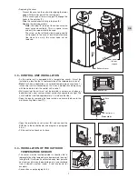
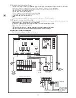
• Replacing the cover.
- Present the cover on the unit while aligning the lower
edge with the lower part of the rear support.
- Fit the cover against the rear support to engage the
hooks in the notches (
1
).
- Slide the cover downward fully into place (
2
).
- Replace the retaining screws.
.
Note:
the screw (
T
) on top of the unit ensures the
cover's ground continuity. This is a special screw
and only this model should be used.
. The screw on the left-hand side is used primarily
for transport. In the case of insufficient clearance
(too close to a wall), this screw need not be
replaced.
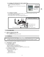
3.3 - CONTROL UNIT INSTALLATION
• As the control unit is equipped with a temperature sensor, it must be
installed in a location that is representative of the temperature in zone 1.
•
Note:
For 2-zone applications, an ambient temperature sensor (zone 1)
(accessory) can be connected on the 2-zone module thus doing away
with the need to install the control unit in zone 1.
• Wall mounting: the unit must not be installed in corners, on shelves or
behind curtains, near sources or heat or directly exposed to sunlight. The
unit should be installed approximately 1.5 m above the floor.
• Open the box by removing the lower screw and secure the base to the
wall (mounting holes, item (
1
)).
• Open the protective cover (screw (
2
)) and connect the
BUS link to the control board (see diagram in paragraph
4.3.4.).
• Fit the control unit back on its base.
3.4 - INSTALLATION OF THE OUTDOOR
TEMPERATURE SENSOR
• This sensor must be located outside in a location that is
representative of the temperature to be measured (on a wall
facing North / North-west) and located away from parasitic
heat sources (chimney, thermal bridge, etc..) and sheltered
from inclement weather (under a roof overhand, for
example).
• Connection as per paragraph 4.3.4.
1
2
T
Bottom of cover
Lower part of
the rear
support
Align
1
2
Base
Rear view
1.50 m
Control unit
Mini. 20 cm
Summary of Contents for SPW-W366HH58
Page 19: ...19 GB ...
Page 37: ...19 FR ...

