


-11-
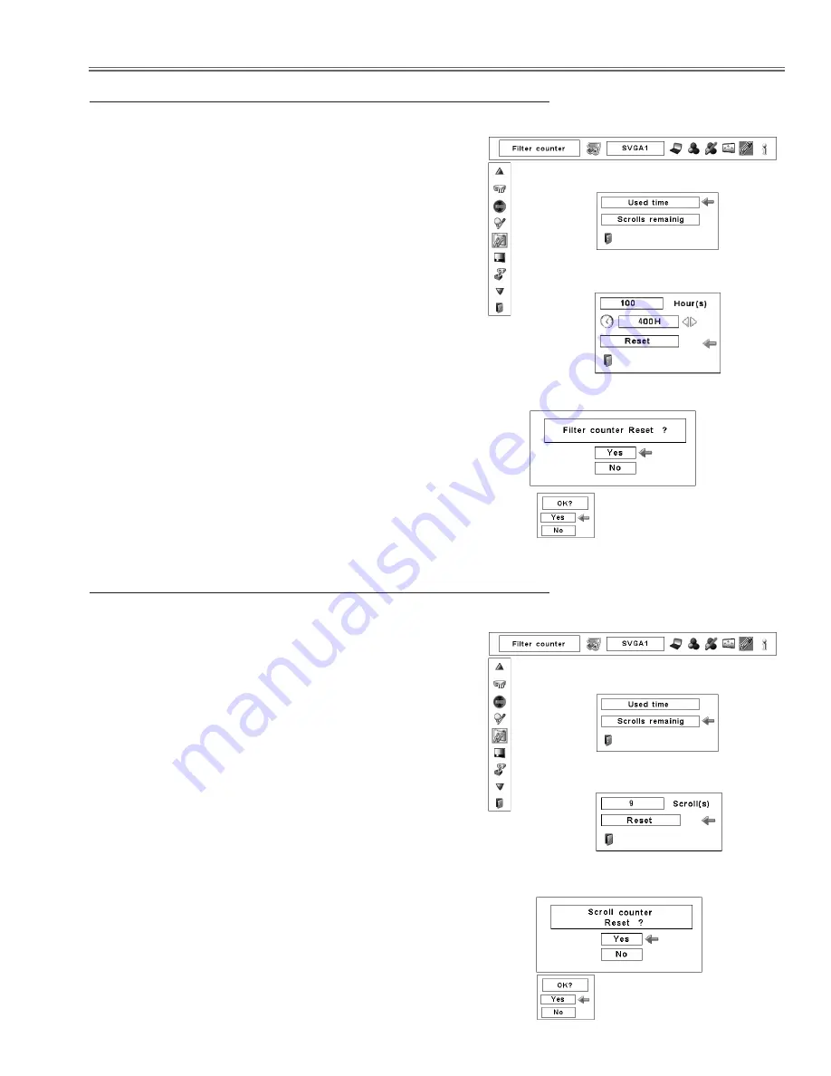
Be sure to reset the Scroll counter after replacing the filter
cartridge.
Press the MENU button to display the On-Screen Menu.
Use the Point
7 8
buttons to move the red frame pointer
to the Setting Menu icon.
Use the Point
ed
buttons to move the red frame pointer
to Filter counter and then press the SELECT button. A
dialog box appears showing the Used time option and
the Scrolls remaining option. Use the Point
ed
buttons
to select Scroll(s) remaining.
1
2
Resetting the Scroll Counter
Scroll counter
Another confirmation dialog box appears, select [Yes] to
reset the Scroll counter.
3
Scroll(s) remaining shows the number of the remaining
scrolls and the Reset option. Select Reset and the “Scroll
counter Reset?” appears. Select [Yes] to continue.
4
Be sure to reset the Filter counter after replacing the filter
cartridge.
Press the MENU button to display the On-Screen Menu.
Use the Point
7 8
buttons to move the red frame pointer
to the Setting Menu icon.
Use the Point
ed
buttons to move the red frame pointer
to Filter counter and then press the SELECT button. A
dialog box appears showing the Used time option and
the Scrolls remaining option. Use the Point
ed
buttons
to select Used time.
1
2
Resetting the Filter Counter
Filter counter
Select Reset and the “Filter
counter Reset?” appears.
Select [Yes],
then another
confirmation
box appears.
Select [Yes] again to reset
the Filter counter.
Another confirmation dialog box appears, select [Yes] to
reset the Filter counter.
3
Used time shows the total accumulated time of the filter
use, a timer setting option, and the Reset option. Select
Reset and the “Filter counter Reset?” appears. Select
[Yes] to continue.
4
Select “Used time” and the dia-
logue box below appears.
Select “Scrolls remaining” and
the dialogue box below appears.
Select Reset and the “Scroll
counter Reset?” appears.
Select [Yes],
then another
confirmation
box appears.
Select [Yes] again to reset
the Scroll counter.
Meintenance
Summary of Contents for PLV-WF20
Page 164: ... 164 Parts Location Diagrams KY3 WF2000 MIrror R Assembly S06 L13 Relay In Assembly L11 ...
Page 166: ... 166 Parts Location Diagrams KY3 WF2000 L15 L12 L16 In the Optical Lamp Unit ...
Page 211: ...Key No Part No Description Key No Part No Description KY3 WF2000 211 Electrical Parts List ...
Page 212: ... KY3A Feb 2008 DC 300 Printed in Japan SANYO Electric Co Ltd ...