-18-
Optical Parts Disassemblies
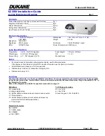
When mounting or assembling the optical parts in the optical unit, the
parts must be mounted in the specified location and direction as
shown in figure below.
5
8
9
Fig.9
2
4
1
The printed marker
comes this side.
13
3
7
10
Locations and Directions
6
12
1
Mirror (W)
2
Integrator lens (OUT)
3
Prism beam splitter (PBS)
4
Dichroic mirror (B)
5
Condenser lens (OUT)
6
Dichroic mirror (G)
7
Relay lens (IN)
8
Mirror (R)
9
Condenser lens (R)
10
Condenser lens
11
Condenser lens (B)
12
Optical filter (UV cut)
13
Mirror (B)
Key No.
Description
The printed marker
comes this side.
11
Note: The arrows in the figure are indicated that
there are the direction of part placement.
Place each part as the printed marker on the
part comes to each arrow direction.
Summary of Contents for PLC-XU45
Page 48: ... 48 CXA2101AQ RGB Matrix IC4101 IC Block Diagrams BA7078AF Selector IC6241 ...
Page 49: ... 49 CXD2064Q Digital Comb Filter IC2101 L3E01031 Level Shift IC3531 IC3561 IC Block Diagrams ...
Page 51: ... 51 ML60851 USB I F IC9801 M62393 D A IC2571 IC Block Diagrams ...
Page 52: ... 52 TA1318N AFC Detector IC6171 TB1274AF Video Decoder IC1101 IC Block Diagrams ...
Page 54: ... 54 ...
Page 82: ...ME3 XU4500 MF3 XU4600 82 47 44 44 47 44 44 Mechanical Parts List 47 57 56 47 47 Optical Parts ...
Page 83: ...ME3 XU4500 MF3 XU4600 83 44 44 54 67 Red 68 Green 69 Blue 45 45 45 Mechanical Parts List ...
Page 86: ...ME3 XU4500 MF3 XU4600 86 Mechanical Parts List 58 70 63 71 57 60 65 59 64 66 51 55 62 ...
Page 88: ... ME3A Mar 2003 BB 400 Printed in Japan SANYO Electric Co Ltd ...
Page 98: ...A10 PCB_ME3A ...
Page 113: ...1 2 3 4 5 6 7 8 9 A B C D E F G H I J K L A18 15 Schematic Diagrams PLC XU45 46 Page A18 Left ...