background image

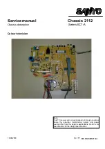
Service Manual SM CE14A2-C
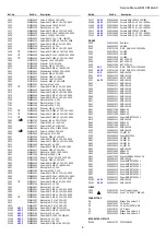
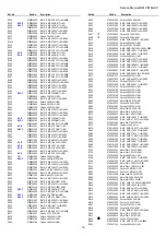
Ref. No.

Part No.

Description

Ref. No.

Part No.

Description

8

C423

0240136010

Ceramic  1000 pF. 10% 100V.

C424

0230600504

Ceramic SMD 100 nF. 10% 25V. 0805

C425

0270342603

Policarbonate  100 nF. 5% 63V.

C426

0250320769

Electrolytic 10 µF. 16V.

C427

0230600504

Ceramic SMD 100 nF. 10% 25V. 0805

C428

0230480600

Ceramic SMD 10 nF. +80-20% 50V 0805

C429

0240136010

Ceramic  1000 pF. 10% 100V.

C430

0230740003

Ceramic SMD 2,2 µF. 10V. +80-20%

C431

0230440125

Ceramic SMD 4700 pF. 10% 50V. 0805

C433

0230240327

Ceramic SMD 100 pF. 5% 50V. 0805

C434

0250320769

Electrolytic 10 µF. 16V.

C435

0230600504

Ceramic SMD 100 nF. 10% 25V. 0805

C438

!

0230360406

Ceramic SMD 1000 pF. 10% 50V.  0805

C440

!

0230480600

Ceramic SMD 10 nF. +80-20% 50V 0805

C441

!

0230360406

Ceramic SMD 1000 pF. 10% 50V.  0805

C600

0270220726

Polyester  10 nF. 10% 250V.

C601

0270301039

Polyester  47 nF. 5% 63V.

C603

0270381080

Polyester  220 nF. 10% 63V.

C611

0230600603

Ceramic SMD 100 nF. +80-20% 25V.

C651

0260210604

Polypropylene 8200 pF 3,5% 1600V

C653

0270410004

Polyester  390 nF. 5% 250V.

C655

0270100522

Polyester  1000 pF. 10% 400V.

C656

0270290802

Polyester  39 nF. 5% 400V.

C657

0270210628

Polyester  8200 pF. 10% 250V.

C668

0250323201

Electrolytic 10µF 160V

C670

!

0230240327

Ceramic SMD 100 pF. 5% 50V. 0805

C674

0230520405

Ceramic SMD 22 nF. 10% 50V. 0805

C675

0230600504

Ceramic SMD 100 nF. 10% 25V. 0805

C676

0230680308

Ceramic SMD 470 nF. 10% 16V. 0805

C678

0230680308

Ceramic SMD 470 nF. 10% 16V. 0805

C700

0250461464

Electrolytic 100 µF. 35V.

C701

0250461464

Electrolytic 100 µF. 35V.

C702

0250461464

Electrolytic 100 µF. 35V.

C703

0270381080

Polyester  220 nF. 10% 63V.

C711

!

0230360406

Ceramic SMD 1000 pF. 10% 50V.  0805

C713

!

0230360406

Ceramic SMD 1000 pF. 10% 50V.  0805

C714

!

0230360406

Ceramic SMD 1000 pF. 10% 50V.  0805

C800

!

0270342702

Polyester  100 nF. 20% 275V.AC

C801

0240134767

Ceramic 1000 pF. +-20% 1KV.

C802

0240134767

Ceramic 1000 pF. +-20% 1KV.

C803

0250464369

Electrolytic.  100 µF. 385V. 22X35

C804

!

0240136135

Ceramic  1000 pF. 20% 4KV

C806

0250210861

Electrolytic 0,47 µF. 50V.

C807

0270140338

Polyester  2200 pF. 10% 63V.

C809

0230300204

Ceramic SMD 330 pF. 10% 50V. 0805

C810

0230360406

Ceramic SMD 1000 pF. 10% 50V.  0805

C811

0250412962

Electrolytic 47 µF. 50V.

C812

0230240327

Ceramic SMD 100 pF. 5% 50V. 0805

C813

0270100431

Polyester  1000 pF. 10% 63V.

C850

0250465002

Electrolytic.  100µF. 160V. 16X25

C851

0250572468

Electrolytic 1000 µF. 16V.

C852

0240470708

Ceramic  220 pF. 5% 1KV. PULSE SL

C853

0270140338

Polyester  2200 pF. 10% 63V.

C854

0230360406

Ceramic SMD 1000 pF. 10% 50V.  0805

C856

0230600603

Ceramic SMD 100 nF. +80-20% 25V.

C857

0250320769

Electrolytic 10 µF. 16V.

C858

0250461266

Electrolytic 100 µF. 16V.

C859

0230640401

Ceramic SMD 220 nF. 10% 16V. 0805

C860

0230480600

Ceramic SMD 10 nF. +80-20% 50V 0805

C900

0230320301

Ceramic SMD 470 pF. 10% 50V. 0805

C901

!

0230240327

Ceramic SMD 100 pF. 5% 50V. 0805

C902

0250320769

Electrolytic 10 µF. 16V.

C903

0250410867

Electrolytic 47 µF. 16V.

C904

0230320301

Ceramic SMD 470 pF. 10% 50V. 0805

C905

0230320301

Ceramic SMD 470 pF. 10% 50V. 0805

C906

0230320301

Ceramic SMD 470 pF. 10% 50V. 0805

C909

!

0230320301

Ceramic SMD 470 pF. 10% 50V. 0805

C910

0250414307

Electrolytic N.P. 47 µF 20% 10V

C911

0250414307

Electrolytic N.P. 47 µF 20% 10V

C912

0250414307

Electrolytic N.P. 47 µF 20% 10V

C1400

AS2-F

0230360406

Ceramic SMD 1000 PF.10% 50V.

C1401

AS2-F

0230600603

Ceramic SMD 100 NF.+80-20% 25V.

C1402

AS2-F

0250320769

Electrolytic 10 µF. 16V.

C1403

AS2-F

0230480600

Ceramic SMD 10 NF. +80-20% 50V.

C1404

AS2-F

0250280864

Electrolytic 4,7 µF. 25V.

C1405

AS2-F

0250280864

Electrolytic 4,7 µF. 25V.

C1406

AS2-F

0230600603

Ceramic SMD 100 nF.+80-20% 25V.

C1407

AS2-F

0230360406

Ceramic SMD 1000 pF.10% 50V.

C1408

AS2-F

0230740003

Ceramic SMD 2,2 µF. 10V. +80-20%

C1409

AS2-F

0230740003

Ceramic SMD 2,2 µF. 10V. +80-20%

C1410

AS2-F

0230740003

Ceramic SMD 2,2 µF. 10V. +80-20%

C1411

AS2-F

0230360406

Ceramic SMD 1000 pF.10% 50V.

C1412

AS2-F

0230740003

Ceramic SMD 2,2 µF. 10V. +80-20%

C1413

AS2-F

0230740003

Ceramic SMD 2,2 µF. 10V. +80-20%

DIODES
D100

0360126304

Red 3mm.

D102

0360130819

1N 4148

D103

0790701106

R.M.G. SMD 0 

 1/10W. 0805

D104

0360130819

1N 4148

D105

0360130819

1N 4148

D106

0360130819

1N 4148

D107

0360111009

BAT 42 DO 35

D108

0360111009

BAT 42 DO 35

D109

0360111009

BAT 42 DO 35

D200

A2-C

0790701106

R.M.G. SMD 0 

 1/10W. 0805

D200

AS2-F

0790701106

R.M.G. SMD 0 

 1/10W. 0805

D200

A2-E

0360601512

SMD LS4148

D201

A2-E

0360601512

SMD LS4148

D250

0360706014

HZT33-02 RE

D251

AS2-F

0360601512

SMD LS4148

D302

0360601512

SMD LS4148

D303

0360601512

SMD LS4148

D400

0360601512

SMD LS4148

D600

0360601512

SMD LS4148

D601

0360601512

SMD LS4148

D606

0360601512

SMD LS4148

D607

0360601512

SMD LS4148

D611

0360601512

SMD LS4148

D651

0360601512

SMD LS4148

D652

0360601512

SMD LS4148

D661

0360377006

ERB44-04

D662

0360378400

ERB06-13

D663

0360377006

ERB44-04

D674

0360602411

Zener SMD BZT55C6V2

D675

0360601512

SMD LS4148

D680

0360377006

ERB44-04

D681

0360377006

ERB44-04

D685

0360601512

SMD LS4148

D700

0360601512

SMD LS4148

D701

0360130629

1N 4007 RL

D703

0360005409

Zener BZX79C24

D800

0360130629

1N 4007 RL

D801

0360130629

1N 4007 RL

D802

0360130629

1N 4007 RL

D803

0360130629

1N 4007 RL

D804

0360601512

SMD LS4148

D806

0360376909

ERB44-02

D850

0360376404

ERB44-06

D851

0360377303

Schottky ERB84-009 90V 2A

D852

0360601512

SMD LS4148

D901

0360602213

Zener SMD BZT55C5V1

D902

0360602213

Zener SMD BZT55C5V1

D904

0360602213

Zener SMD BZT55C5V1

D905

0360602213

Zener SMD BZT55C5V1

D906

0360602213

Zener SMD BZT55C5V1

D907

0360602213

Zener SMD BZT55C5V1

D908

0360602213

Zener SMD BZT55C5V1

D1200

AS2-F

0360601512

SMD LS4148

D1201

AS2-F

0360601512

SMD LS4148

FUSES
F-800

0760100701

Fuse Terminal Taped

F800

0330110503

Fuse T 2 A./250V.  TIME-LAG

CONNECTORS
FB

0330144007

Ribbon Wire Holder 2 P.

FC

0330270307

2P. Socket

FE

0330115106

2P. Socket X RTM 1/6/8

FF

0330129701

4 P. Socket

FG

0330144205

Ribbon Wire Holder 4 P.

FI

0330163304

Ribbon Wire Holder 8 P.

INTEGRATED CIRCUITS
IC100A

0360516702

ST92185B1B1

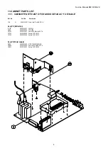
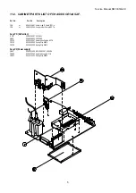
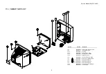
Summary of Contents for CE14A2-C

Page 1: ...E14A2 E 4 11 2 CABINET PARTS LIST OF CHASSIS CE14AS2 F 5 11 3 CABINET PARTS LIST 6 12 PARTS LIST 7 CE14A2 C CE14A2 E CE14AS2 F Service Manual Models CRT 14 Philips A34EAC01X06 CHASSIS 2112 EC7 A Colour Television Give complete SERVICE PART No for parts order or servicing it is shown on the rating sheet on the cabinet back of the TV set Note This TV receiver will not work properly in foreign countr...

Page 2: ...ly adjustment and high voltage adjustment to maintain the high voltage within the specified limits COMPLIANCE TO STANDARDS All of those marked with or must be replaced with original parts WARNING This TV set contains components which are particularly sensitive to static electricity ESD It is recommended that all due precaution be taken handling integrated circuits and semiconductors 4 Recommendati...

Page 3: ...rect selection to any program from the remote control device Audio Power rating 1W rms 10 distortion Speakers 1 of 8 Ω Aerial External aerial sockets 75 Ω IEC Jack for headphones Mono jack 3 5mm Clock and alarm Function Timer Function Switch on and off of CTV programmable in real time AV connectors 1 Scart connector 21 pin CENELEC standard AV RGB and S_Video 1 RCA Video input frontal 1 RCA Audio i...

Page 4: ...me of the model CE14A2 C 3 Instruction manual 9 MOUNTED CIRCUITS CODES CE14A2 C CE14A2 E CE14AS2 F 6110372809 6110375802 6110375604 Main Socket TRC PCB s 7110017204 7110018707 7110018608 Main PCB 7040003506 7040003506 7040003506 Socket TRC PCB 10 ABBREVIATIONS USED IN THE PARTS LIST AND CABINET PARTS LIST Note The following abbreviations indicate A2 C Exclusive parts for CE14A2 C A2 E Exclusive pa...

Page 5: ...12907 Comp side IF shield EC7 A Assy PD Deflection IC701 0360516207 LA7840L Q650 0360308902 2SD2599 YR701 0200225407 Heatsink Deflection EC7 A YR702 0010106300 Spring CLIP 56379 YR703 0010106300 Spring CLIP 56379 Assy PF Power supply Q800 0360311005 MOS 2SK3067 600V 2A YR800 0200225506 Heatsink SOURCE EC7 A YR801 0010110401 Spring CLIP 56363 ...

Page 6: ...080113004 Cooper side IF shield EC7 A Assy PD Deflection IC701 0360516207 LA7840L Q650 0360308902 2SD2599 YR701 0200225407 Heatsink deflection EC7 A YR702 0010106300 Spring Clip 56379 YR703 0010106300 Spring Clip 56379 Assy PF Power supply Q800 0360311005 MOS 2SK3067 600V 2A YR800 0200225506 Heatsink source EC7 A YR801 0010110401 Spring Clip 56363 ...

Page 7: ...g YP13 0130214109 Button Power 17 E7E5 YP14 0130214604 PUSHKey Assy 14 E8R8 YP15 0090257700 Degaussing Coil 14 YF 1 2700049014 Front Cabinet Assy 14 E8R8 YF 2 0590269411 Back Cover 14 E8R8 AENOR YF 6 A2 C 0390246817 Rating Plate CE14A2 C YF 6 AS2 F 0390247005 Rating Plate CE14AS2 F YF 6 A2 E 0390247203 Rating Plate CE14A2 E YF23 0890161326 Screw HI LO 5 8X27 W Washer YF24 0890191315 Screw AR 4X15 ...

Page 8: ...00 nF 80 20 25V C111 0250320769 Electrolytic 10 µF 16V C112 0230600603 Ceramic SMD 100 nF 80 20 25V C114 0230360406 Ceramic SMD 1000 pF 10 50V 0805 C115 0250461266 Electrolytic 100 µF 16V C116 0230240327 Ceramic SMD 100 pF 5 50V 0805 C117 0230160327 Ceramic SMD 22 pF 1 50V 0805 C118 0230440125 Ceramic SMD 4700 pF 10 50V 0805 C123 0230440125 Ceramic SMD 4700 pF 10 50V 0805 C124 0230600603 Ceramic S...

Page 9: ...Electrolytic 47 µF 16V C904 0230320301 Ceramic SMD 470 pF 10 50V 0805 C905 0230320301 Ceramic SMD 470 pF 10 50V 0805 C906 0230320301 Ceramic SMD 470 pF 10 50V 0805 C909 0230320301 Ceramic SMD 470 pF 10 50V 0805 C910 0250414307 Electrolytic N P 47 µF 20 10V C911 0250414307 Electrolytic N P 47 µF 20 10V C912 0250414307 Electrolytic N P 47 µF 20 10V C1400 AS2 F 0230360406 Ceramic SMD 1000 PF 10 50V C...

Page 10: ...ad 0 6 mm L701 0470040007 Jumper Lead 0 6 mm L702 0470040007 Jumper Lead 0 6 mm L800 0090413709 Mains Filter 2X19 MH 250 VAC 0 5A L801 0090318668 Peaking Coil 1 µH 20 I MAX 270MA L802 0470040007 Jumper Lead 0 6 mm L850 0620005504 Ferritebead 3 5X6 80 Ω 100 MHz L851 0620005504 Ferritebead 3 5X6 80 Ω 100 MHz L853 0620005504 Ferritebead 3 5X6 80 Ω 100 MHz L900 0620011502 Ferrite SMD 0603 600 Ω 20 MHz...

Page 11: ...8409 Carbon 120 Ω 5 1 2W R316 0790248009 R M G SMD 5 6 KΩ T 5 0805 R317 0790111207 Carbon 4 7 Ω 5 1 4W R319 0790160501 Carbon 56 KΩ 5 1 6W R400 0790126700 Carbon 100 Ω 5 1 6W R401 0790126700 Carbon 100 Ω 5 1 6W R402 0790151500 Carbon 10 KΩ 5 1 6W R403 0790227003 R M G SMD 100 Ω T 5 0805 R404 0790227003 R M G SMD 100 Ω T 5 0805 R405 0790227003 R M G SMD 100 Ω T 5 0805 R406 0790234702 R M G SMD 430 ...

Page 12: ...G SMD 47 KOHM T 5 R1206 AS2 F 0790245005 R M G SMD 3 3 KOHM T 5 R1401 AS2 F 0790229009 R M G SMD 150 OHM T 5 R1402 AS2 F 0790243000 R M G SMD 2 2 KOHM T 5 R1403 AS2 F 0790741805 R M G SMD 1 5 KOHM T 5 R1404 AS2 F 0790846109 R M G SMD 220 OHM T 5 R1406 AS2 F 0790243000 R M G SMD 2 2 KOHM T 5 R1411 AS2 F 0790247001 R M G SMD 4 7 KOHM T 5 R1412 AS2 F 0790245005 R M G SMD 3 3 KOHM T 5 R1415 AS2 F 0790...

Page 13: ...P C B CARA COMPONENTES P C B COMPONENTS SIDE P C B LATO COMPONENTI P C B LATO SOLDATURE P C B SOLDER SIDE P C B CARA SOLDADURAS ...

Page 14: ... SMD 100 R404 SMD 75 R925 R915 1K SMD SMD XXX R1159 LINE_FILTER L800 D680 ERB44 04 C670 100 SMD R816 1K 1 4W 0 L101 SMD XXX R1403 R712 1 18K 0 4W XXX C1405 SMD 430 R572 0 4W 1 18K R711 D106 1N4148 SMD 4 7K R870 C676 0 47 SMD SMD 3 3K R812 BC858B Q570 0 1 C425 SMD 680 R942 XXX IC100 SMD 47 R533 100u C400 SMD 100K R423 BC848B Q651 SMD XXX R1156 220u C324 400V LS4148 D303 SMD 24V D703 C713 1000SMD C6...

Page 15: ...r television Note This TV receiver will not work properly in foreign countries where the television transmission system and power source differ from the design specifications Refer to the specifications for the design specifications Ref Nº MS CHASSIS2112 I 16 06 2000 ...

Page 16: ...2 1 Ports description 8 4 2 2 Supply 9 4 2 3 Oscillator 9 4 2 4 Reset 9 4 2 5 RGB output character generator 9 4 2 5 1 Character generator synchronism 9 4 2 5 2 RGB output voltage 9 4 2 6 Teletext only for ST92195 version 9 4 2 6 1 Non interlaced 10 4 2 7 PD signal 10 4 2 8 ON signal 10 4 2 9 Radio control signals 10 4 2 10 SC signal 10 4 2 11 SUP_FAIL signal 10 4 2 12 AM SCART signal 10 4 2 13 LP...

Page 17: ...eo filter and switches 16 4 7 1 6 Colour decoder 16 4 7 1 7 RGB processing 16 4 7 1 8 RGB control 16 4 7 1 9 Supply and Bandgap 17 4 7 2 Block diagrams of video paths 17 4 8 AUDIO SIGNAL PROCESSING 17 4 8 1 Audio processor 17 4 8 2 AM sound 17 4 8 3 L system 18 4 8 4 Audio switching 18 4 8 5 Speaker amplifier 19 4 9 RGB AMPLIFIER 19 4 10 CRT SOCKET CONNECTOR 19 4 11 PERIPHERAL CONNECTIONS TO TV SE...

Page 18: ...ary corrective action Carefully follow the instructions for B1 volt power supply adjustment and high voltage adjustment to maintain the high voltage within the specified limits 1 3 Recommendations to protect our environment STAND BY MODE In order to save energy and to maintain an optimum picture quality it is advisable to switch off the TV using the ON OFF button located at the front of TV set USE...

Page 19: ...Sequential selection from the controls on the set Direct selection to any program from the remote control device Audio Power rating 1W rms 10 distortion Speakers 1 of 8 Ω Aerial External aerial sockets 75 ohms IEC Jack for headphones Mono jack 3 5mm Clock and alarm Function Timer Function Switch on and off of CTV programmable in real time AV connectors 1 Scart connector 21 pin CENELEC standard AV ...

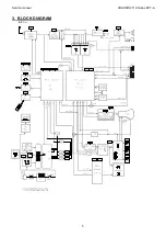
Page 20: ...Service manual CHASSIS 2112 Series EC7 A 5 3 BLOCK DIAGRAM ...

Page 21: ...de B5 Auxiliary output in the primary to supply the control signals that are needed for IC800 4 1 1 Switched Mode Power Supply SMPS 4 1 1 1 IC800 controller start up The supply to the start up of IC800 comes from the C811 load through R805 When the voltage of pin 1 is higher than 14 5 volts threshold voltage the IC begins the oscillation pin3 Once it has started the increase of consumption of the ...

Page 22: ...rom the micro activated at high level Q852 Q851 B1_L 8V polarisation R869 and 5V polarisation In order to achieve a correct IC400 line oscillator start up is necessary that the 8V raises in ramp about 100ms This is obtained with the integrator that Q850 and the circuitry associated to its base forms with the 8V regulator The weak load of the decouplings that there are in 8V also avoids a peak of d...

Page 23: ...r through the OSD and the LED 4 2 1 Ports description In the following table are listed the pins that are connected to some port the related signal names and a basic description of its functionality Functionality Input I or Output O Activ e Level Pin number ST92195 TXT micro Pin number ST92185 Not TXT Related signal Power_Down indicator I L 1 1 PD Supply control 8V and 5V O H 3 3 ON Radio communic...

Page 24: ...e 5V_M is present 4 2 4 Reset This signal is active at low level It initialises the microprocessor whenever the supply is correct Q858 and his periphery generate the reset signal The reset is active when the B2 voltage is lower than 7 4 volts approximately 4 2 5 RGB output character generator A character generator is integrated into the microprocessor The outputs are RGB pins number 17 16 15 and F...

Page 25: ...V to 12V AV mode 4 3 format 4 2 11 SUP_FAIL signal This signal comes from a 5V voltage divider When SUP_FAIL is at low level while the ON signal is at high level means that there is a 8V or 5V failure 4 2 12 AM SCART signal This signal only acts when the IC1401 is present there is AM sound or radio because the SCART sound the AM sound and the RADIO have the same management into the one chip IC400 ...

Page 26: ...f C603 Q600 governs the primary one of T600 In parallel with the primary side of T600 are C601 and R601 key components that limit the Q600 collector maximum peak voltage and they also take part in shaping the Q650 base current The secondary side of T600 attacks the Q650 base L600 is basic and determines the slope of current extraction from Q650 base Its value is defined to cut down the losses of Q...

Page 27: ...istics 4 3 6 EHT discharge The EHT discharge is carried out by means of the following procedure before switching off the TV set the microprocessor sets to 1 a bit in video processor IC400 by means of I2C bus These bit provokes that the video processor duplicates the line frequency for 160 mS at the same time it moves the RGB outputs to white The result the flyback height cuts by half when the line...

Page 28: ...in the vertical deflection circuit that is a danger the vertical flyback disappears The vertical flyback is fed back towards pin 22 of IC400 by means of V_GUARD signal In the case of lacking the pulses of vertical flyback the video processor IC400 activates a bit that is checked through bus I2C by the microprocessor periodically When the reading indicates anomaly the microprocessor shows ERROR_2 T...

Page 29: ...cy control AFC is carried out by the microprocessor checking the tuning voltage based on two bits provided by the video processor IC400 that they contain information about the difference between the tuned frequency and the right frequency See the section video IF later on The tuner gain is controllable by the AGC continuous voltage This voltage is generated by IC400 and makes the automatic control...

Page 30: ...the horizontal oscillator and the horizontal flyback signal generated by the deflection it enters by pin 41 FBISO PHI 2 produces a time shift of the horizontal output pin 40 HOUT thus keeping stable the picture position on the screen The components related to PHI 2 are the connected ones to pin 42 PH2LF The picture phase is adjustable via I2C H SHIFT in the service menu The horizontal output pin 4...

Page 31: ... and B Y demodulator and to the colour identifier The band base signals R Y y B Y is taken to the delay line via PAL SECAM switcher The output of the delay line goes to pins 30 RYO and 29 BYO The SECAM demodulation is carried out with a PLL demodulator The reference voltage generated in pin 16 SECPLL is regulated so that the PLL demodulator output is set at a reference voltage generated internally...

Page 32: ...RV in Service mode In the same way but independently for each channel the adjustment of the white balance is made The microprocessor writes via I2C three adjustments that affect independently to each one of the three colours The adjustment of G and B is accessible in way service the red one is prefixed to a certain value Tube start up When the TV set starts to work the microprocessor monitorises v...

Page 33: ... carrier of 38 9 MHz from the rest of systems to 33 9 MHz Therefore the surface acoustic wave of picture SF200 is intended to work both frequencies of picture carrier in TV sets that have this system As far as the sound the intermediate frequency of its carrier changes from 32 4 MHz with system L to 40 4 MHz with system L Therefore in TV sets with system L the surface acoustic wave SF1400 can be s...

Page 34: ... the chain of RGB modifying the exits of RGB More details see the chapter Video processor 4 10 CRT socket connector The tubes can have internal discharges they go from the anode EHT to any other terminal of CRT Focus G2 G1 cathodes or heaters This phenomenon is most frequently when the tubes are new and it tends to disappear when the TV set has already worked during a time As a main measure to pro...

Page 35: ...vice menu navigation The most important keys in the service menu are Vol scroll down submenus when they are and change the adjustments Vol change the adjustments P scroll the cursor down through the different options P scroll the cursor up through the different options MENU it shows the menu SERVICE if you are in a submenu or it exits from the menu SERVICE if you are inside and numeric keys they a...

Page 36: ...al models ON in export models OSO HV discharge mode ON OFF OFF OFF OEM TV set trademark ON OFF OFF OFF in models SANYO ON in models OEM TUN UK Tuner selection for UK only band UHF ON OFF OFF for no UK models ON for UK models Lp Enable of system L ON OFF OFF in models without L ON in models with L RADIO Enable of radio ON OFF OFF in models without radio ON in models with radio STANDARD PAL B G PAL ...

Page 37: ...nking Visual adjustment Vertical centre Philips pattern Picture Normalised CRT Screen SERVICE GEOMET V S HIFT Adjust to centre the picture in vertical direction Visual adjustment Height Philips pattern Picture Normalised CRT Screen SERVICE GEOMET V AMPL Adjust just to get the checked board hidden Visual adjustment Horizontal centre Philips pattern Picture Normalised CRT Screen SERVICE GEOMET H SHI...

Page 38: ...grated Circuit TDA8841N2 0360515001 Integrated Circuit TDA 8842 N2 J224 0470040007 Jumper LEAD 0 6 MM J241 0470040007 Jumper LEAD 0 6 MM J242 0470040007 Jumper LEAD 0 6 MM J243 0470040007 Jumper LEAD 0 6 MM J246 0470040007 Jumper LEAD 0 6 MM J251 0470040007 Jumper LEAD 0 6 MM J297 0470040007 Jumper LEAD 0 6 MM J300 0790701106 R M G SMD 0 Ω 1 10W 0805 J306 0790701106 R M G SMD 0 Ω 1 10W 0805 J343 0...

Page 39: ...436 0230150229 Ceramic SMD 18 PF 1 50V After making the modification it is necessary to enter the Service Menu STANDARD sub menu to change option NTSC M to ON Now TV set is prepared to receive NTSC M signals by means of euroconnector or frontal AV not by means of aerial 6 3 Procedure of substitution of microprocessor IC100 The run pilot production began with micros version OTP One Time Programmabl...

Page 40: ... is initialised it removes the data contained in the NVM to load those that the microprocessor has by default therefore it is obligatory to introduce again the configuration data CONFIG standards STANDARD and the adjustments of Service Menu not manual adjustments see Adjustments For that reason it is better not re initialise the NVM if it is not strictly necessary as it is in the case of substitut...

Page 41: ... before 200msec Signal ON is disabled and it is shown a failure of the supply ERROR_4 7 Video processor starts If there is no answer it will be shown ERROR_1 8 HOUT signal is enabled pin 40 of IC400 at which the deflections are started If there are anomalies it will appear ERROR_2 or ERROR_3 9 The corresponding channel is tuned and the Mute signal is disabled pin 52 of IC100 10 It waits until the ...

Page 42: ...or of IC400 damaged Fault in path between IC400 and IC701 C656 open ERROR_3 Short or open circuited heaters Short circuit in some secondary of T650 Q650 damaged Driver stage does not work correctly Short circuit from cathode to ground ERROR_4 Overconsumption in the power supply General failure in voltage regulators ERROR_6 IC125 damaged ERROR_11 Generic error of I2C bus 7 6 Protection inhibition I...

Page 43: ...ge IC125 Check the continuity of I2C bus to the pins 5 and 6 of IC125 OK OK Check C656 Check C700 and D701 Change IC701 YES NO ERROR_2 Check the vertical deflection path to IC701 Switch on the TV set with PL103 key pressed inhibited protections Increase G2 just to light the screen Does picture spread over the whole screen Check the path of V_GUARD signal Check the ramp generator pin 51 of IC400 Po...

Page 44: ...ply of the driver circuit Possibly X400 damaged Failure of T650 OK OK No Yes No Yes No Possible short circuit of heaters The pulses are OK Possibly Leakage in C402 or C403 Bandgap capacitance OK Check the horizontal deflection path Possible faulty in the protection circuits D562 D561 D504 D505 Check that the voltage at DEFL_FAIL is 5V Check the patch from pin 40 of IC400 to Q600 base Bad Possibly ...

Page 45: ... 8V path to R861 No Check a possible short circuit at 8V Check Q853 Q854 Q859 Q860 and its periphery Are the voltage B1_L in R869 No Check Q851 Q852 and periphery No Yes 7 7 4 Error 11 ERROR_11 Check short circuits to ground in lines SDA or SCL Check IC400 Switch on the TV set with Mkey pressed inhibited protections Check IC400 IC400 Check if the voltage at pin 8 is lower than before R401 IC125 Ch...

Page 46: ...ge level in secondaries windings Check 5V_M No Yes Possible failure of IC800 Is R822 fused Probable failure of Q800 N 1 Probable failure of secondary diodes No Yes Does the led make ON OFF cycles do not mistake for ERROR_1 No No The protection is performing due to overvoltage Yes Check B6 Check Q801 and its periphery Check the voltage at pin 14 of IC800 N 1 If there is a failure of Q800 it is stro...

Page 47: ...ks FLYBACK Signal produced in the line transistor connector during the return of the beam sweeping It is also called flyback to the time lapse of the beam return HEATER CRT cathode heating filaments I TV system Audio carrier is 6MHz above the video carrier I2C Serial communication bus with two lines SDA for data and SCL for clock IF Intermediate frequency IR Infrared L French TV system Positive vi...

Page 48: ......

Reviews: