Service manual
CHASSIS 2112-Series EC7-A
15
The AGC controls the gain of IF amplifier so that the video amplitude maintains constant. The modulated video is
taken to an AGC detector, which controls directly the gain of IF stages. The AGC time constant is determined by the
capacitor connected to pin 53 (DECAGC).
The AGC of tuner reduces its gains in case of receiving strong signal from R.F. The point in which the gain
reduction of the tuner begins is programmable via I2C (AGC in service menu).
The AFC information is available in two bits. They are accessible for the microprocessor via I2C. This information is
used in the tuning and pursuit of broadcasters.
The section of video identifications controls several bits that are accessible for the microprocessor via I2C. This
information is used both in the tuning of channels and in the mutes management.
4.7.1.3
Horizontal and vertical synchronisation.
There are the following sections in synchronisation:
#
Horizontal synchronism separator.
#
Horizontal
oscillator.
#
PHI-1
detector.
#
PHI-2
detector.
#
Horizontal
output.
#
Coincidence
detector.
#
Vertical synchronism separator.
#
Vertical divider with counter.
The input to horizontal synchronism separator is the video signal selected (the video that is on the screen). The
synchronism separator slices synchronism pulse in the mid point. The DC level is fixed to the video input. The black
level is stored internally.
The horizontal oscillator is internal, there are no external components related to it. The adjustment of its nominal
frequency is made with an internal calibration circuit that uses as reference the quartz crystal of 4.43MHz connected
to pin 35 (X400). The horizontal oscillator generates a sawtooth signal to the double of the line frequency. Once
calibrated, the oscillator is controlled by PHI-1 loop with the intention of synchronising it with the signal of video
input.
The PHI-1 detector is a PLL circuit that synchronises the horizontal oscillator with the video input signal. The
components related to PHI-1 are the connected ones to pin 43 (PH1LF). The time constant of PHI-1 is controlled by
the microprocessor via I2C, as well as by the noise detector.
Detector PHI-2 provides a stable position of the picture in the screen. It is necessary because the time of storage of
the line transistor (Q650) varies with the beam current, causing different delays in the deflection circuit. The PHI-2
detector compares the horizontal oscillator and the horizontal flyback signal generated by the deflection (it enters by
pin 41, FBISO). PHI-2 produces a time shift of the horizontal output (pin 40, HOUT), thus keeping stable the picture
position on the screen. The components related to PHI-2 are the connected ones to pin 42 (PH2LF). The picture
phase is adjustable via I2C (H. SHIFT in the service menu).
The horizontal output (pin 40, HOUT) is an open collector type. In normal conditions it has a duty cycle of 45% in
high level and 55% in low level. In the start-up transient has a frequency of 31,25KHz, after 50mS it changes to its
nominal frequency. With this, a soft start-up of the horizontal deflection is obtained. In the stop transient, it changes
its nominal frequency to a frequency of 31,25KHz. This, combined with the activation of the RGB, discharges the
EHT. It also provides a soft deflection stop.
The coincidence detector enables a bit when the video signal is synchronized with the horizontal oscillator. This bit
is accessible for the microprocessor via I2C. This bit is used in the mutes' management.
The vertical synchronism separator separates the vertical synchronism pulse from the video input signal. This pulse
is used later to trigger the counter system for the vertical.
The vertical divider uses a counter that provides the timing for the ramp generator in the geometry processor. The
clock of the counter is taken from the horizontal oscillator. This system assures a good interlace.
4.7.1.4 Geometry
processor.
In the geometry processor block, there are the following options:
#
Vertical ramp generator.
#
Vertical geometry processor.
#
Horizontal geometry processor (E/W).
#
Geometry
compensation.
The vertical ramp generator provides the reference signal for the vertical and horizontal geometry processors. A
current reference is generated internally in order to load the ramp capacitor. R426 is connected to pin 52 (IREF)
and it is used to generate the current reference. It is a Metal Film resistor with 1% tolerance in order to give
temperature stability and minimise the spreads of picture geometry. C425 is connected to pin 51 (VCS) and it is the
ramp capacitor. It is made of polycarbonate to give temperature stability.
The vertical geometry processor generates the signal that outputs balanced by pins 47 (VDRA) and 46 (VDRB).
Later, this signal is amplified and taken to the deflector coil. The adjustment parameter is accessible via I2C
(V.SLOPE, V.AMPL, S-CORR, V.SHIFT in service menu).
The geometry compensation input (pin 50, EHTO) modulates the dimension of the vertical signal to maintain stable
the height of the picture in the screen.
Summary of Contents for CE14A2-C
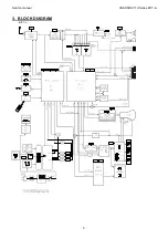
Page 20: ...Service manual CHASSIS 2112 Series EC7 A 5 3 BLOCK DIAGRAM ...
Page 48: ......

