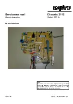


Service manual
CHASSIS 2112-Series EC7-A
14
phase is moved towards the left and injecting current it is moved toward the right. So, the distortions, due to phase
deviations, are corrected
4.5.3 ABL
description.
The ABL is the limiting circuit of average beam current. The goal of this circuit is avoiding that the average beam
current surpasses the 870
µ
A. This takes place reducing the resistance and the brightness, in case of being
necessary.
4.5.3.1
BCL signal generation.
R682, R683, R688, C674, C675, C676 and C678 form a low-pass filter that filters the BCI signal. From it, a
continuous voltage is obtained that is applied to the base of Q673, which is formed like an emitter follower. The
signal BCL is present in the Q673 transmitter.
4.5.3.2
Contrast and brightness reduction.
The contrast reduction (and eventually of the brightness) is carried out by the video processor.
The BCL signal is applied by means of D400 and R430 to pin 22 of video processor (IC400). This pin has two
functions: During the vertical retrace it is the V_GUARD input (see Vertical protections), and during the sweeping it
is the input of beam current limiter (see description of the video processor).
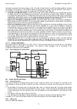
4.6
Tuner and tuning circuit.
The tuner TU250 allows the reception of all TV by broadcasting and via cable. For it, it distributes all the rank of
channel frequencies in three bands (LB, HB and U) whose selection is carried out by the microprocessor (IC100).
The tuning is a synthesis voltage type: the tuned channel depends on the tuning voltage. This one is a continuous
voltage in the rank of 0V to 28V approximately. This voltage initially is generated by the microprocessor as width
modulated pulse train (PWM) that later it is amplified and low-pass filtered by the circuit whose active components
are D250 and Q251. The automatic frequency control (AFC) is carried out by the microprocessor checking the
tuning voltage based on two bits provided by the video processor, IC400, that they contain information about the
difference between the tuned frequency and the right frequency. (See the section “video IF” later on). The tuner gain
is controllable by the AGC continuous voltage. This voltage is generated by IC400 and makes the automatic control
of gain is made. (Also see section "Video IF").
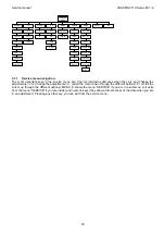
4.7
Video signal processing.
4.7.1 Video
processor.
The video processor is IC400.
Inside IC400 there are the following blocks:
#
Video
IF
#
Mono sound (not used in this chassis)
#
Horizontal and vertical synchronisation.
#
Geometry
processor.
#
Video filters and switches.
#
Colour
decoder.
#
RGB
Processing.
4.7.1.1
Video processor versions.
The possible versions of video processor are
TDA8841
!
!
!
!
used in deflection 90ºmodels without SECAM.
TDA8842
!
!
!
!
used in deflection 90º models with SECAM.
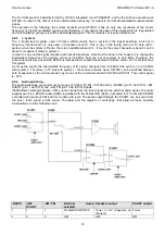
4.7.1.2 IF
video.
The following sections are in the IF video:
#
IF
amplifier.
#
PLL and VCO demodulator.
#
Video
buffer.
#
AGC.
#
Tuner
AGC.
#
AFC
#
Video
Identification.
The signal that comes from the tuner output (TU250) is applied to the surface acoustic wave SF200, which lets
pass the carriers with information of sound and video. The output of SF200 is applied to IF amplifier which has
symmetrical inputs.
The IF signal is demodulated with a PLL detector. The PLL is used to generate a reference signal that is in phase
with the video carrier. The demodulation is obtained multiplying this reference with the IF signal. The demodulator
can handle positive video (case of SECAM L/L') and negative video (the rest of the TV systems).
The VCO does need neither adjustment nor external coil. The frequency selection is carried out by the
microprocessor by means of bus I2C. The components related with PLL are the connected ones to pin 5 (PLLLF).
The video buffer adapts the levels and output impedance so that the signal can be later treated. The demodulated
video goes out by pin 6 (IFVO) and has a typical level of 2Vpp.
Summary of Contents for CE14A2-C
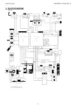
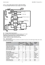
Page 20: ...Service manual CHASSIS 2112 Series EC7 A 5 3 BLOCK DIAGRAM ...
Page 48: ......