IV-9
SM831148
4. Service procedures
1
2
3
4
5
6
No
No
No
No
No
No
No
Yes
Yes
Yes
Yes
Yes
Yes
Yes
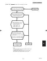
Replace outdoor unit
control PCB.
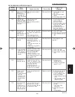
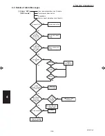
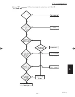
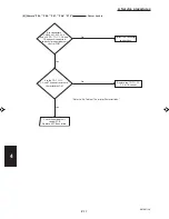
(2) [Alarm “P26”]
HIC PCB trouble)
IGBT short-circuit protection on inverter control (IPDU) PCB
Is power OK?
Correct power line.
Are
circuit wiring,
connector
connections, and
reactor
connections
OK?
Correct.
Has filter PCB
RY001 or RY002
relay activated?
Has filter PCB
AC fuse blown?
Replace filter PCB.
Disconnect
U.V.W. output
terminal on HIC PCB and
start operation.
Does alarm
“P26”
occur?
Replace HIC PCB.
Is
compressor OK?
(Check for layer
short circuit.)
Replace compressor.
Is
resistance
between
each terminal on
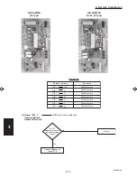
HIC PCB OK?
(See following
page.)
Check HIC PCB.
Replace if PCB
has failed.
Summary of Contents for 000 BTU Ductless Single Zone Mini-Split Wall-Mounted Heat Pump
Page 2: ......
Page 77: ...1 2 3 4 5 6 I 73 SM831148 1 Specifications 1 4 Dimensional Data B Outdoor Unit CH4272R C4272R ...
Page 118: ......
Page 128: ...1 2 3 4 5 6 III 10 SM831148 3 Electrical data Wall Mounted Type KH2672R ...
Page 129: ...III 11 SM831148 3 Electrical data 1 2 3 4 5 6 Wall Mounted Type KH2672R Schematic Diagram ...
Page 133: ...III 15 SM831148 3 Electrical data 1 2 3 4 5 6 Wall Mounted Type KHH2672R Schematic Diagram ...
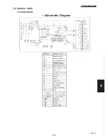
Page 135: ...III 17 SM831148 3 Electrical data 1 2 3 4 5 6 3 2 Outdoor Units CH2672R Schematic Diagram ...
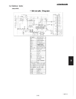
Page 137: ...III 19 SM831148 3 Electrical data 1 2 3 4 5 6 3 2 Outdoor Units C2672R Schematic Diagram ...
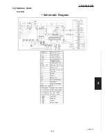
Page 143: ...III 25 SM831148 3 Electrical data 1 2 3 4 5 6 3 2 Outdoor Units CH4272R Schematic Diagram ...
Page 145: ...III 27 SM831148 3 Electrical data 1 2 3 4 5 6 3 2 Outdoor Units C4272R Schematic Diagram ...
Page 146: ......

