


IV-13
SM831148
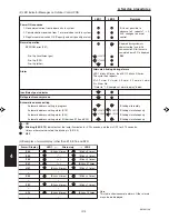
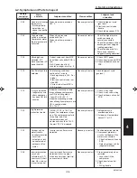
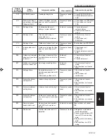
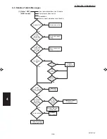
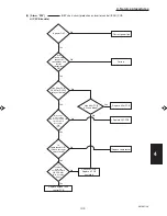
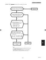
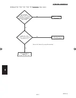
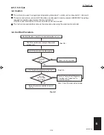
4. Service procedures
1
2
3
4
5
6
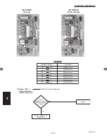
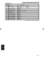
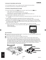
Sensor installation
Sensor
Sensor type
Sensor
Sensor type
s
s
e
r
d
d
a
s
s
e
r
d
d
a
n
o
i
t
a
c
o
l
00
Room temp.
05
–
(temp. used for control)*
01
Remote controller temp.
06
Discharge temp.
Indoor unit
02
Indoor intake temp.
07
–
03
Indoor heat exchanger temp. (E1 )
08
–
04
Indoor heat exchanger temp. (E2 )
09
–
0A
Discharge temp. (TD )
12
–
0b
–
13
–
0C
–
14
Current
(AC current)
Outdoor unit
0d
Intake temp. (TS )
15
Outdoor electronic control
valve position
0E
Outdoor heat exchanger temp. (C1 )
16
–
0F
Outdoor heat exchanger temp. (C2 )
17
–
10
–
18
–
11
Outdoor air temp.
19
–
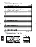
Sensor Temperature Correlation Table
* Main unit only when group control is enabled
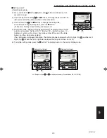
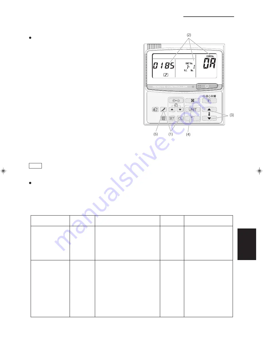
Figure: Sample display when discharge
temperature at unit No. 1-1 is 185˚F
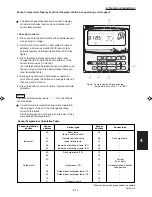
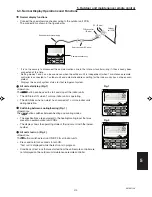
Sensor Temperature Display Function (Displayed both when operating and stopped)
The below check procedure can be used to display
all remote controller, indoor unit, and outdoor unit
sensor temperatures.
<Check procedure>
(1) Press and hold the button and button simultaneously
for 4 seconds or longer.
(2) Unit No. X-X (main unit No.), item code XX (sensor
address), and service monitor 00XX (sensor tem-
perature) appear on the remote controller LCD. (See
figure.)
(3) Press the temperature setting and buttons and
change the item code to the sensor address of the
sensor that you want to monitor.
(For the relationship between the sensor address and
the sensor type, refer to the below Sensor Tempera-
ture Correlation Table.)
(4) During group control and simultaneous operation
multi control, press the button and change to the unit
that you want to monitor.
(5) Press the button to return to normal remote controller
operation.
NOTE
The temperature display reads “- - - - ” for units that are
not connected.
If monitor mode is selected during normal operation,
the only parts of the LCD that change are those
shown in the figure.
All other displays do not change, and remain as they
were during normal operation.
Summary of Contents for 000 BTU Ductless Single Zone Mini-Split Wall-Mounted Heat Pump
Page 2: ......
Page 77: ...1 2 3 4 5 6 I 73 SM831148 1 Specifications 1 4 Dimensional Data B Outdoor Unit CH4272R C4272R ...
Page 118: ......
Page 128: ...1 2 3 4 5 6 III 10 SM831148 3 Electrical data Wall Mounted Type KH2672R ...
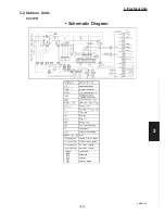
Page 129: ...III 11 SM831148 3 Electrical data 1 2 3 4 5 6 Wall Mounted Type KH2672R Schematic Diagram ...
Page 133: ...III 15 SM831148 3 Electrical data 1 2 3 4 5 6 Wall Mounted Type KHH2672R Schematic Diagram ...
Page 135: ...III 17 SM831148 3 Electrical data 1 2 3 4 5 6 3 2 Outdoor Units CH2672R Schematic Diagram ...
Page 137: ...III 19 SM831148 3 Electrical data 1 2 3 4 5 6 3 2 Outdoor Units C2672R Schematic Diagram ...
Page 143: ...III 25 SM831148 3 Electrical data 1 2 3 4 5 6 3 2 Outdoor Units CH4272R Schematic Diagram ...
Page 145: ...III 27 SM831148 3 Electrical data 1 2 3 4 5 6 3 2 Outdoor Units C4272R Schematic Diagram ...
Page 146: ......