


1
2
3
4
5
6
II-2
SM831148
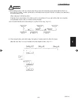
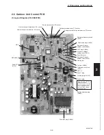
2. Processes and functions
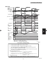
Fig. 1
(THERMO. OFF)
(THERMO. ON)
ROOM TEMP.
THERMO. ON
5 MINUTES
MORE THAN
5 MINUTES 3 MINUTES
SET TEMP
COMPRESSOR
OUTDOOR FAN
(H OR M)
INDOOR FAN
OFF
OFF
OFF
OFF
1
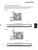
1. Refer to 2-4 Outdoor Fan Speed Control
MORE THAN
3 MINUTES
MORE THAN
5 MINUTES
ON
ON
ON
ON
ON
ON
SET SPEED
T+2
°
F
T–2
°
F
. T
°
F
BODY SENSOR
1133_THS_I
THERMO. OFF
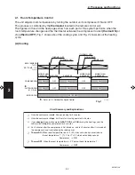
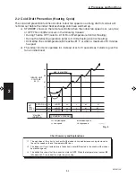
Chart Summary and Explanations
Once the compressor
starts
, it keeps running for 5 minutes.
Once the compressor
stops
, it will not start running again for 3 minutes.
If you
change
the operation mode (
HEAT
,
COOL
or
FAN
) during the heating cycle, the
control circuit
stops
the compressor for 3 minutes.
For 5 minutes after the compressor is first turned on, and for 3 minutes after it is turned off,
the compressor is not controlled by the room sensor.
Thermo ON:
When room temperature rises 2 F (4˚F when set on body sensor) above
the set temperature T˚, (T˚+2˚F or T˚+4˚F when set on body sensor):
Compressor
ON
Thermo OFF
: When the room temperature is –2˚F below the set temperature T˚:
Compressor
OFF
2-1
Room Temperature Control
The unit adjusts room temperature by turning the outdoor unit’s compressor ON and OFF.
This process is controlled by the
thermostat
located in the remote control unit.
The figures on this and the next pages show how each part of the system performs when the
room temperature changes and the thermostat activates the compressor to start
(thermo ON)
or
stop
(thermo OFF)
. Fig. 1 shows about the cooling cycle, and Fig. 2 shows about the heating
cycle.
(A) Cooling
Summary of Contents for 000 BTU Ductless Single Zone Mini-Split Wall-Mounted Heat Pump
Page 2: ......
Page 77: ...1 2 3 4 5 6 I 73 SM831148 1 Specifications 1 4 Dimensional Data B Outdoor Unit CH4272R C4272R ...
Page 118: ......
Page 128: ...1 2 3 4 5 6 III 10 SM831148 3 Electrical data Wall Mounted Type KH2672R ...
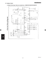
Page 129: ...III 11 SM831148 3 Electrical data 1 2 3 4 5 6 Wall Mounted Type KH2672R Schematic Diagram ...
Page 133: ...III 15 SM831148 3 Electrical data 1 2 3 4 5 6 Wall Mounted Type KHH2672R Schematic Diagram ...
Page 135: ...III 17 SM831148 3 Electrical data 1 2 3 4 5 6 3 2 Outdoor Units CH2672R Schematic Diagram ...
Page 137: ...III 19 SM831148 3 Electrical data 1 2 3 4 5 6 3 2 Outdoor Units C2672R Schematic Diagram ...
Page 143: ...III 25 SM831148 3 Electrical data 1 2 3 4 5 6 3 2 Outdoor Units CH4272R Schematic Diagram ...
Page 145: ...III 27 SM831148 3 Electrical data 1 2 3 4 5 6 3 2 Outdoor Units C4272R Schematic Diagram ...
Page 146: ......