


KBox E-410-APL - User Guide, Rev. 1.0
// 35
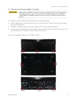
Figure 11: Clamping the KBox E-410-APL onto the DIN rail (Horizontal Installation)
7.1.2.
VESA Mounting
Depending on the ordered KBox E-410-APL configuration, your system may be supplied with a VESA mounting kit
(Figure 12). The kit consists of two parts: a base bracket (Figure 12, pos. 1) to be fixed permanently on the mounting
surface and another hooked bracket to hold the KBox E-410-APL with a hand-screw knob (Figure 12, pos. 2) to secure
two brackets.
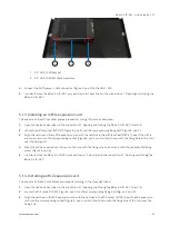
Figure 12: Optional VESA mounting kit
1
Base Mounting Bracket
2
Hooked Mounting Bracket with a Hand-screw Knob
The base mounting bracket complies with VESA 75 and VESA 100 patterns (Figure 13). To fasten the bracket, the
control cabinet / custom enclosure / machine / monitor / wall must have VESA 75, VESA 100 or other screw pattern
shown as Figure 13 for mounting.
Figure 13: Hole pattern of base mounting kit for KBox E-410-APL
2
1