


KBox E-410-APL - User Guide, Rev. 1.0
// 28
4.
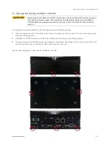
Lift the access cover up.
5.
Now you have access to the internal DDR3L SO-DIMM, 2.5" SATA HDD / SSD, mPCIe and M.2 connectors / slots /
sockets respectively in order to remove or install hardware components.
6.
For closing replace carefully the access cover to the system and screw it on with the retained screws.
7.
Tighten the retained screws when the cover is firmly in place.
When used as intended, the KBox E-410-APL is to operate only in closed condition.
Only when the access cover is properly fixed with the screws and the front side with
WLAN antennas are properly installed and secured with the screws, it is ensured that
the user does not have access to the internal parts of the KBox E-410-APL.
5.1.1.
Installing SO-DIMM memory modules
To install SO-DIMM memory modules please proceed according to the steps described:
1.
Open the device as described in the subsection 5.1 "Opening and Closing the KBox E-410-APL" (step 1-5).
2.
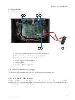
Locate the SO-DIMM memory sockets (DIMM1 & DIMM2) (Figure 3, pos. 1).
3.
Align the notches on the SO-DIMM memory modules with the notches in the SO-DIMM memory sockets (DIMM1
& DIMM2). Insert the SO-DIMM memory modules into the corresponding sockets (Figure 3, pos. 1) at a 30-degree
angle.
4.
Rotate the SO-DIMM memory modules down until they snap into place and the levers close.
5.
In order to close the KBox E-410-APL, proceed step 6 & 7 described in the subsection 5.1 "Opening and Closing the
KBox E-410-APL".
5.1.2.
Installing an HDD / SSD
To install a 2.5" HDD / SSD please proceed according to the steps described:
1.
Open the device as described in the subsection 5.1 "Opening and Closing the KBox E-410-APL" (step 1-5).
2.
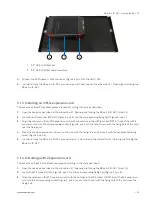
Align one side of the HDD / SSD's screw holes with the fixing pins (Figure 4, pos. 2) of the hard disk bracket and
slide in.
3.
Align the other side of the HDD / SSD's screw holes with the screw holes (Figure 4, pos. 3 & Figure 6, pos. 1) of the
hard disk bracket and then screw the HDD / SSD to the bracket.
Figure 6: Installing an HDD / SSD