


20 S&C Instruction Sheet 466-500
Operation
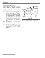
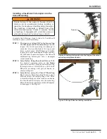
Figure 15� A correct fastening approach�
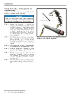
Figure 16� A correct fastening approach�
Follow these steps when using S&C’s Loadbuster tool:
STEP 1�
Check for proper resetting of the Loadbuster
tool by extending the tool about 3 inches
(76 mm) by hand. Throughout this travel, an
increasing spring resistance should be felt.
STEP 2�
Fasten the Loadbuster tool to an S&C Universal
Pole not less than 6 feet (183 cm) long (8 feet
[244 cm] for catalog number 5400R3) with the
frame of the tool in line with the pole. As shown
in Figures 15 and 16, the Loadbuster tool must
be attached so it reaches across the front of the
VacuFuse II Self-Resetting Interrupter, and the
Loadbuster tool’s anchor must be hooked to the
attachment hook on the far side of the
VacuFuse II interrupter.
The Loadbuster tool should never be attached
with its anchor hooked on the closest side of
the VacuFuse II interrupter, as shown in
Figures 17 and 18 on page 21. Attaching the
tool in this manner will not only obscure the
operator’s line of vision, but it could also result
in bending stress on the tool, causing improper
disengagement.
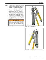
STEP 3�
Swing the Loadbuster tool toward the
VacuFuse II Self-Resetting Interrupter and pass
the Loadbuster pull-ring hook through the pull-
ring on the VacuFuse II Self-Resetting
Interrupter. The pull-ring latch will deflect and,
upon complete entry of the pull-ring, will spring
back, locking the Loadbuster tool to the pull-
ring. The Loadbuster tool is now connected
across the upper contacts of the VacuFuse II
Self-Resetting Interrupter, as shown in
Figure 19 on page 22.


