


18 S&C Instruction Sheet 466-500
Operation
Removing the VacuFuse II Interrupter from
the Cutout Mounting
WARNING
DO NOT attempt to remove a VacuFuse II Self-
Resetting Interrupter from its cutout mounting with
the vacuum interrupter in the
Closed position . The
vacuum interrupter is in the
Closed position when the
POSITION indicator at the base of the VacuFuse II
interrupter displays a red target . Removing the
VacuFuse II interrupter from its cutout mounting with
the vacuum interrupter in the
Closed position may
cause arcing, equipment damage, serious injury, or
death .
Complete the following steps to remove the VacuFuse II
interrupter from its cutout mounting:
STEP 1�
Open the vacuum interrupter inside the
VacuFuse II interrupter by pulling down on the
yellow manual operating lever. Confirm the
POSITION indicator at the base of the
VacuFuse II interrupter displays a green target.
STEP 2�
Wait one minute and 45 seconds until the
VacuFuse II Self-Resetting Interrupter drops
out.
If the VacuFuse II Self-Resetting Interrupter
st ays i n it s cutout mou nt i ng, con f i r m
the POSITION indicator at the base of the
VacuFuse II interrupter displays a green target.
Use the troubleshooting guide on page 23 to
determine the cause of the unit remaining in
the cutout mounting and the appropriate action
to take.
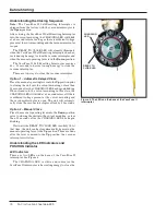
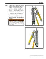
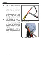
STEP 3�
Removal Using Gloved Hands:
Remove the
VacuFuse II Self-Resetting Interrupter from its
cutout mounting with gloved hands, as shown in
Figure 14.
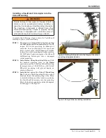
STEP 4�
Removal Using the Talon Handling Tool:
Attach a Talon Handling Tool to a short hotstick.
Insert the curled prong of the Talon tool into the
lifting eye of the trunnion, and raise the
VacuFuse II interrupter out of the mounting.
See Figure 9 on page 13.
Figure 14� Removing the VacuFuse II interrupter with
gloved hands�


