


S&C Instruction Sheet 466-500 13
Installation
Installing a VacuFuse II Interrupter into the
Cutout Mounting
WARNING
Provide training to line crews on the use of both a
hotstick and an extendostick before installing or
operating the VacuFuse II Self-Resetting Interrupter .
The VacuFuse II interrupter is different from other
cutout-mounted devices . Failure to properly handle
a VacuFuse II interrupter with a hotstick and/or an
extendostick may lead to serious injury or death .
Complete the following steps to install a VacuFuse II
interrupter into a cutout mounting:
STEP 1�
If using an existing S&C cutout mounting
or other approved cutout mounting:
Visually
inspect the cutout mounting for damage or
excessive wear, particularly in the upper and
lower contact areas. If ANY damage is visible,
replace the cutout mounting before proceeding.
DO NOT install and/or energize a VacuFuse II
Self-Resetting Interrupter into a damaged
cutout mounting.
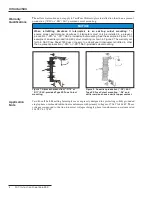
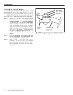
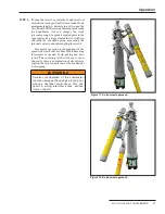
STEP 2�
Installation Using Insulated Gloves:
With
the manual operating lever in the
Down
position, insert the VacuFuse II Self-Resetting
Interrupter into a 110-kV BIL or a 125/150-kV
BIL-rated mounting with gloved hands, as
shown in Figure 8.
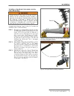
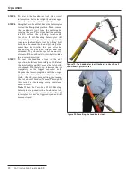
STEP 3�
Installation using the Talon™ Handling
Tool:
Attach a Talon Handling Tool to a short
hotstick. Insert the curled prong of the Talon
tool into the lifting eye of the trunnion, and raise
the VacuFuse II interrupter into the mounting.
Rotate the hotstick counterclockwise 180 degrees
to disengage it. See Figure 9.
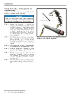
Figure 8� Guiding the trunnion into the hinge of the cutout
mounting using gloved hands�
Trunnion
Figure 9� Using a Talon tool during installation�


