S&C VacuFuse II Installation And Operation Manual Download Page 16

16    S&C Instruction Sheet 466-500

Operation

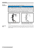
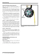
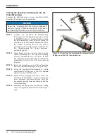
Figure 11� The manual operating lever in the Up position� 

Manual operating 
lever

If Maintenance Is to Be Performed on the 

Transformer

Follow these steps if maintenance is to be performed on the 
transformer:

STEP  1�  

Open the vacuum interrupter inside the VacuFuse II 
Self-Resetting Interrupter by moving the manual 
operating lever to the 

Down 

position firmly using 

the straight prong of the Talon tool or a distribution 
prong. See Figure 11.
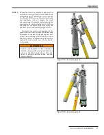
STEP  2�  

After the VacuFuse II Self-Resetting Interrupter 
opens and drops out (after approximately 


1 minute and 45 seconds), remove the unit from its 
mounting, if required by utility practice. Follow 
the steps in the “Removing the VacuFuse II 
Interrupter from the Cutout Mounting” section 
starting on page 18. This creates a visible “open 
gap” showing the transformer is isolated from the 
feeder. Depending on your utility’s standard 
practices, additional grounds may be required.

STEP  3�  

Follow your utility’s standard practice for 
performing transformer maintenance. After any 
necessary maintenance or repairs have been 
completed, install the VacuFuse II Self-Resetting 
Interrupter and close it into the mounting 
following the steps described in the “Installation” 
section starting on page 12.

Opening and Closing the VacuFuse II 

Interrupter

 WARNING

The VacuFuse II Self-Resetting Interrupter is designed 
to protect distribution transformers from internal and 
external fault current . A VacuFuse II interrupter found in 
the 

Open and Drop Out position (POSITION indicator 

displaying a green target) should NOT be closed until 
the cause of the trip operation has been determined and 
repaired . Closing without repairing the fault could result 
in equipment damage, injury, or death .

The vacuum interrupter inside the VacuFuse II Self-Resetting 
Interrupter can be opened using the yellow manual operat-
ing lever on the side of the VacuFuse II interrupter, with 
or without power. The interrupter must be closed in the 
cutout mounting with sufficient voltage present for at least 
45 seconds before the vacuum interrupter can be closed by 
moving the lever to the 

Closed

 position. 

Summary of Contents for VacuFuse II

Page 1: ...and Handling 8 Inspection 8 Packing 8 Handling 8 Storage 8 Returning 8 Before Starting 9 VacuFuse II Interrupter Parts 9 Understanding the Closing Sequence 10 Understanding the LED Indicators and POSI...

Page 2: ...They are not intended to be a substitute for adequate training and experience in safety procedures for this type of equipment NOTICE Thoroughly and carefully read this instruction sheet before install...

Page 3: ...ATES TO THE GOODS DESCRIBED HEREIN ANY DESCRIPTION THAT RELATES TO THE GOODS OR ANY REMEDIAL PROMISE INCLUDED IN PRICE SHEET 150 OR PRICE SHEET 153 Warranty For VacuFuse II Self Resetting Interrupters...

Page 4: ...warranty set forth in S C Price Sheet 150 does not apply to a VacuFuse II interrupter retrofitted in other than a present production R10 or R11 S C provided cutout mounting VacuFuse II Self Resetting...

Page 5: ...can result in product or property damage if instructions are not followed If any portion of this instruction sheet is unclear and assistance is needed contact the nearest S C Sales Office or S C Auth...

Page 6: ...mber A WARNING A VacuFuse II Self Resetting Interrupter must be dropped out from the cutout mounting to be considered OPEN and de energized Device may be energized from either side G 9842 DANGER B TCC...

Page 7: ...ys consider all parts live until de energized tested and grounded 6 OPERATING TOOLS To close a VacuFuse II Self Resetting Interrupter use a conventional insulated hotstick or S C Universal Pole and Po...

Page 8: ...ing hardware for securing the cutout mounting to the pole if specified Handling NOTICE DO NOT DROP the VacuFuse II Self Resetting Interrupter or subject any of its parts to undue stress during install...

Page 9: ...h the parts of the VacuFuse II Self Resetting Interrupter See Figure 3 Figure 3 An overview of the VacuFuse II Self Resetting Interrupter POSITION indicator CHARGING LED Manual operating lever Hinge e...

Page 10: ...it into the cutout mounting or less than 35 seconds after the CHARGING LED has begun blinking When closed into the cutout mounting in this state the CHARGING LED will blink at a 1 second interval if t...

Page 11: ...ontains a highly reflective visible red or green target that indicates the position of the vacuum interrupter inside the VacuFuse II Self Resetting Interrupter The target is green when the vacuum inte...

Page 12: ...cuFuse II interrupter cutout mounting to a suitable mounting bracket as illustrated in Figure 7 Tighten the carriage bolt nut until snug but loose enough to permit pivot adjustment Note the placement...

Page 13: ...ar particularly in the upper and lower contact areas If ANY damage is visible replace the cutout mounting before proceeding DO NOT install and or energize a VacuFuse II Self Resetting Interrupter into...

Page 14: ...g Sequence section on page 10 STEP 2 Stand firmly in front of and in line with the cutout mounting Do not operate standing directly underneath the VacuFuse II Self Resetting Interrupter If using an ex...

Page 15: ...he reclosing event the unit will lock out and drop out from the cutout mounting Note that non reclosing VacuFuse II interrupters will lock out and drop out from the cutout mounting every time the devi...

Page 16: ...ty s standard practice for performing transformer maintenance After any necessary maintenance or repairs have been completed install the VacuFuse II Self Resetting Interrupter and close it into the mo...

Page 17: ...nterrupter will trip open independently of any force still applied to the manual operating lever To Reset the Manual Operating Lever After Manually Closing into Fault Current When the VacuFuse II inte...

Page 18: ...g lever Confirm the POSITION indicator at the base of the VacuFuse II interrupter displays a green target STEP 2 Wait one minute and 45 seconds until the VacuFuse II Self Resetting Interrupter drops o...

Page 19: ...rupter that is in the Closed position without using a loadbreak tool such as S C s Loadbuster tool An arc started by opening a VacuFuse II Self Resetting Interrupter under load without a loadbreak too...

Page 20: ...ol s anchor must be hooked to the attachment hook on the far side of the VacuFuse II interrupter The Loadbuster tool should never be attached with its anchor hooked on the closest side of the VacuFuse...

Page 21: ...a trigger inside the tool will trip releasing the charged spring separating the internal contacts and interrupting the circuit Successful operation is independent of the speed with which the VacuFuse...

Page 22: ...and pull ring at the same time by twisting the pole after the Loadbuster tool has been tripped and fully extended To perform this operation smoothly always roll the Loadbuster tool so that it rotates...

Page 23: ...urs the unit will go into its End of Life state Topreventprematureendoflife useLoadbuster The S C Loadbreak Tool to operate the VacuFuse II interrupter into the Dropout position Refer to the Operation...

Reviews: