


10 S&C Instruction Sheet 466-500
Before Starting
Understanding the Closing Sequence
Note:
The VacuFuse II Self-Resetting Interrupter is
shipped from the factory with the vacuum interrupter in
the
Open
position.
After closing the VacuFuse II Self-Resetting Interrupter
into the cutout mounting, the CHARGING LED will blink
at a 1-second interval as long as there is sufficient voltage
present at the cutout mounting and the vacuum interrupter
is open.
The READY TO CLOSE LED will steadily illuminate
when the VacuFuse II Self-Resetting Interrupter has har-
vested enough energy to close the vacuum interrupter and
when the manual operating lever is in the
Down
position.
The VacuFuse II Self-Resetting Interrupter requires
45 ± 10 seconds to harvest enough energy to close the
vacuum interrupter.
There are two ways to close the vacuum interrupter:
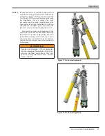
Option 1 – Automatic Delayed Close
Place the manual operating lever into the
Up
position prior
to closing the unit into the cutout mounting, or less than
35 seconds after the CHARGING LED has begun blinking.
When closed into the cutout mounting in this state, the
CHARGING LED will blink at a 1-second interval if there
is sufficient voltage present at the cutout mounting and
the vacuum interrupter is open. The unit will automati-
cally close the vacuum interrupter after 45 ± 10 seconds.
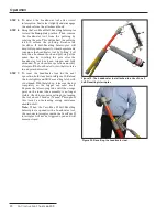
Option 2 – Manual Close
Place the manual operating lever into the
Down
position
prior to closing the unit into the cutout mounting, or less
than 35 seconds after the CHARGING LED has begun
blinking.
Wait until the READY TO CLOSE LED is solidly lit. At
that time, the unit can be closed manually by moving the
manual operating lever to the
Up
position. Three seconds
after the lever is moved to the
Up
position, the vacuum
interrupter will close.
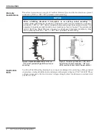
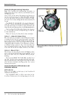
Understanding the LED Indicators and
POSITION Indicator
LED Indicators
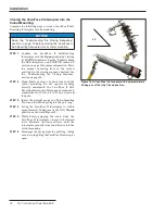
There are two LEDs on the base of the VacuFuse II
interrupter. See Figure 4.
The CHARGING LED is white and indicates the
VacuFuse II interrupter is harvesting energy to close the
Figure 4� The LEDs on the base of the VacuFuse II
interrupter�
CHARGING
LED
READY TO
CLOSE LED


