


12 S&C Instruction Sheet 466-500
Installation
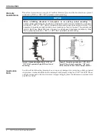
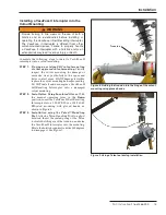
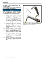
Carriage-bolt
Carriage bolt nut
Lockwasher
Mounting
bracket
Overhead pole-
top mounting
center insert
External
tooth
lockwasher
Figure 7� Attaching an overhead pole-top style VacuFuse II
interrupter cutout mounting to the mounting bracket�
Installing the Cutout Mounting
If a VacuFuse II interrupter is ordered without a cutout
mounting, proceed to the “Installing a VacuFuse II
Interrupter into the Cutout Mounting” section on page 13.
Complete the following steps to install the cutout
mounting for the VacuFuse II Self-Resetting Interrupter:
STEP 1�
Attach the VacuFuse II interrupter cutout
mounting to a suitable mounting bracket, as
illustrated in Figure 7. Tighten the carriage bolt
nut until snug but loose enough to permit pivot
adjustment. Note the placement of the external-
tooth lockwasher between the mounting
bracket and the center insert of the mounting.
Note:
A mounting bracket suitable for crossarm,
pole, or wall mounting is furnished only if
specified through the addition of suffix “-B”
or “-C” to the VacuFuse II interrupter catalog
number.
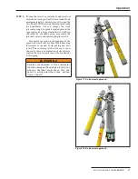
STEP 2�
Pivot the mounting to a position that will
provide maximum ease of operation and then
securely tighten the carriage-bolt nut.
STEP 3�
Make electrical connections. When using
aluminum conductors, be sure to wire-brush
them and apply a coating of oxidation inhibitor
before inserting them into the mounting’s
connectors.


