background image

8    S&C Instruction Sheet 461-521

Quick Pairing Guide

 After a gateway is powered, either on the utility pole or in the service center, it can be 
connected to and programmed using a PC. To connect to the communications gateway 
with a PC:

STEP  1.  

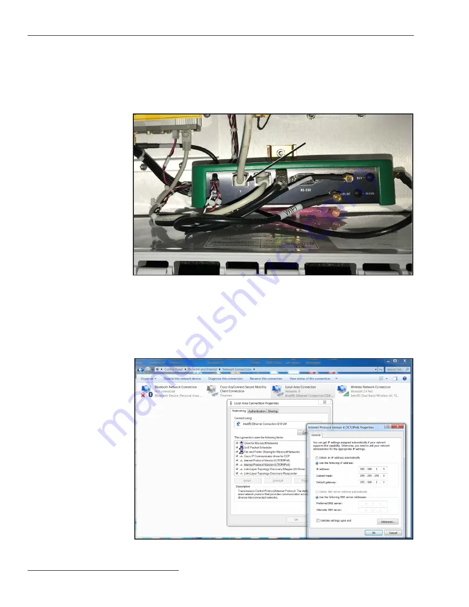
Connect a CAT5 Ethernet cable to the Ethernet port on the PC. Connect the 
other end of the Ethernet cable to Ethernet Port 1 on the green gateway 
controller module inside the communications gateway cabinet, see Figure 2. 

Connecting to 

a TripSaver II 

Communications 

Gateway with a PC

Ethernet cable

Figure 2. Connect an Ethernet cable to the gateway controller module.

STEP  2.  

The communications gateway is accessed using a web browser interface. The 
default configuration of the communications gateway’s IP gateway is 192.168.1.1 
with DHCP set to 

On

. To join the communications gateway network, set the 

PC’s network address to “Obtain an IP Address Automatically” and “Obtain 
DNS Server Address Automatically” under the PC’s LAN address settings to 
enable a network connection to the communications gateway. Alternately, a 
static IP address within the 192.168.1.x network may be used. See Figure 3.

Figure 3. Setting a static IP address on a PC to connect to the communications gateway.

Summary of Contents for TripSaver II

Page 1: ...rstanding Safety Alert Messages 3 Following Safety Instructions 3 Replacement Instructions and Labels 3 Location of Safety Labels 4 Safety Precautions 5 Shipping and Handling Packing 6 Inspection 6 Ha...

Page 2: ...ns Gateway Designate a location where you can easily retrieve and refer to this publication Proper Application WARNING The equipment in this publication is only intended for a specific application The...

Page 3: ...recautions are not followed NOTICE NOTICE identifies important procedures or requirements that can result in product or property damage if instructions are not followed Following Safety Instructions I...

Page 4: ...for Safety Labels Location Safety Alert Message Description Part Number A DANGER TripSaver II may be energized from either side and in any position G 9473 E B CAUTION This control is connected to ele...

Page 5: ...ctric shock and death DANGER The TripSaver II Cutout Mounted Recloser operates at high voltage Failure to observe these precautions will result in serious personal injury or death Some of these precau...

Page 6: ...TICE DO NOT drop a TripSaver II recloser or subject any of its parts to undue stress during installation Only remove a TripSaver II recloser from the carton when you are ready for installation Storage...

Page 7: ...rvice center configuration software Overview BeforepairingaTripSaverIICutout MountedRecloserwithaTripSaverIICommunications Gateway it must be placed in Gateway mode at the service center To enable Gat...

Page 8: ...s Gateway with a PC Ethernet cable Figure 2 Connect an Ethernet cable to the gateway controller module STEP 2 The communications gateway is accessed using a web browser interface The defaultconfigurat...

Page 9: ...from the command prompt With the CAT5 cable attached to communications gateway Ethernet Port 1 launch a Web browser on the PC Within the URL address line type in the communications gateway default IP...

Page 10: ...h firmware version 1 6 or 1 7 pairing can only be performed with the TripSaver II recloser powered by line current or an external power source not supplied by S C For details on the specifications for...

Page 11: ...asily paired in the service center without the requirement of line current or an external power source using the corded power module and ac adapter from the service center configuration kit STEP 1 Pla...

Page 12: ...e 9 This will turn on communications inside the TripSaver II recloser allowing it to be paired with the communications gateway Figure 9 Attach the magnet tool to the green logo STEP 4 Navigate to the...

Page 13: ...n be used at the installation site on TripSaver II reclosers furnished with firmware version 1 8 installed on the utility pole and NOT powered by line current by using the cordless power module to sup...

Page 14: ...on the Device Management screen STEP 2 With the recloser removed from the utility pole connect to the TripSaver II recloser using the service center configuration software and the service center confi...

Page 15: ...rvice center configuration software can be found in S C Instruction Sheet 461 504 STEP 4 Navigate to the Communication Settings menu and click on the Communication Mode dropdown box Change the Communi...

Reviews: