


10 S&C Instruction Sheet 461-521
Quick Pairing Guide
STEP 4.
After a successful login, the browser will open to the communications gateway
General Status
screen with an application navigation menu on the left side of
the screen. The navigation menu will remain visible for all subordinate menu
interface screens.
There are two methods of pairing a TripSaver II recloser to work with a communications
gateway that depend on the firmware version of the TripSaver II recloser. The first is
service center programming at the customer’s facility before taking the TripSaver II
reclosers to the installation site. The second is on-site programming, accomplished after
the TripSaver II reclosers and communications gateway have been installed in the field.
In both cases, S&C recommends pairing TripSaver II reclosers one at a time. This will
ensure each device is fully and securely connected before pairing the next device. When
paired, the TripSaver II recloser will only communicate with its paired gateway using a
secure, encrypted protocol. The security keys used to encrypt the communications are
unique to the pair and cannot be transferred between TripSaver II reclosers or gateways.
Field Pairing with the TripSaver II Recloser with Firmware Version 1.6,
1.7 or 1.8 Installed on the Utility Pole and Powered by Line Current
For TripSaver II reclosers furnished with firmware version 1.6 or 1.7, pairing can only
be performed with the TripSaver II recloser powered by line current or an external
power source not supplied by S&C. For details on the specifications for an external
power source, contact your local S&C Sales Office. Use this procedure for pairing a
TripSaver II recloser installed on a utility pole and powered by line current:
STEP 1.
Place the TripSaver II recloser in
Gateway
mode, as described on page 7. Install
the TripSaver II recloser on the utility pole, as described in S&C Instruction
Sheet 461-502, and power the TripSaver II recloser via line current. Power the
communications gateway by connecting it to ac power. Make sure any nearby
USB transceiver is unplugged.
STEP 2.
With the communications gateway installed no more than 100 feet (30.5 meters)
from the TripSaver II recloser to be paired, connect to the communications
gateway with a PC, as described on page 8. (A 25 to 30 foot (7.6 to 9 meter)
distance is more common depending on pole height and local construction
practices.)
STEP 3.
Navigate to the
Device Management
screen. See Figure 7 on page 11.
Pairing a
TripSaver II
Recloser with a
Communications
Gateway
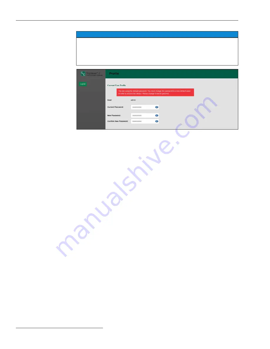
NOTICE
With firmware version 3 .1 and later, the default password for the Admin user must
be changed before proceeding . See Figure 6 . The new non-default password must
be at least 8 characters with at least one uppercase and one lowercase character .
Numbers and special characters are also allowed but not required . <Space>, <Tab>,
<&> characters are not allowed .
Figure 6. The Profile screen for changing the password.


