


627-500
27
Step 31
Refer to the applicable wiring diagram and
make the appropriate connections from the
current sensors (with polarity marked on top)
to the terminal blocks. Then attach each current
sensor to its associated high-voltage cable as
follows:
1. Remove the
¹⁄₄
– 20 gap nut on the current
sensor. With polarity marked on top, open
the current sensor and place it around the
appropriate high-voltage cable. Now replace
and securely tighten the gap nut.
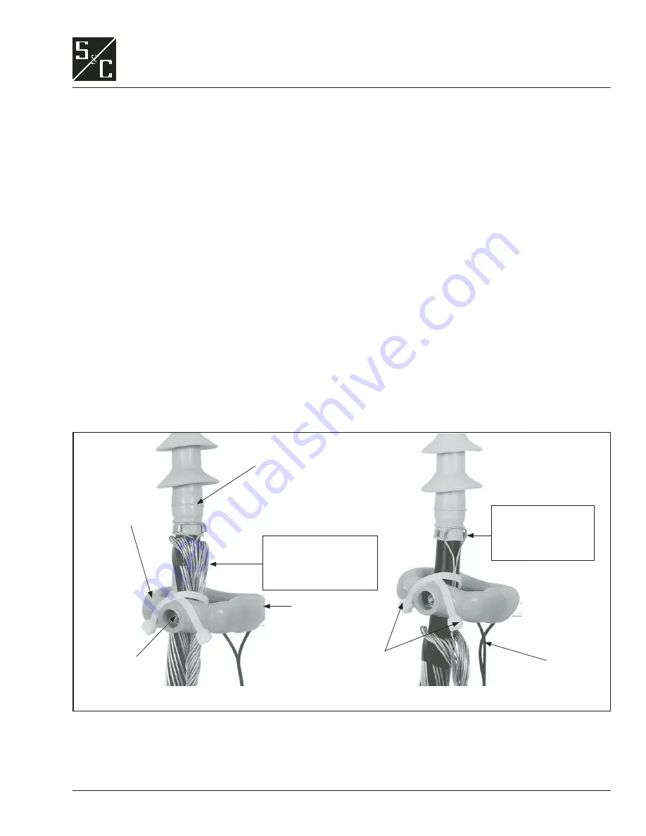
2. Secure the current sensor to the high-voltage
cable
at a point below the cable termina-
tor or stress cone
using the plastic wire
ties furnished. See Figure 24. The current
sensor may be placed against the grounded
concentric neutral of the cable—in which
case the concentric neutral
must
be brought
back through the sensor—or it may be placed
against the semi-conducting jacket of the
cable— in which case the drain wire of the
terminator
must
be brought through the
sensor.
Figure 24. Typical methods for attaching S&C Current Sensor to high-voltage cable.
The terminal blocks furnished with the
optional auxiliary switch, Catalog Number
Suffi x “-C9”; optional remote-indication feature,
Catalog Number Suffix “-Y4”; and optional
supervisory control feature Catalog Number
Suffi x “-Y6” are also located in the terminal
block compartment. Refer to the applicable
wiring diagram and make the connections as
required.
Step 32
Connect the cable concentric-neutral ground
wires and ground pads inside the source-
transfer module to the system grounding
facility in accordance with the user’s standard
grounding practice. Use the equivalent of 4/0
copper cable (or cable sized in accordance with
the user’s standard practice) in either a single or
a multiple connection to realize the maximum
momentary rating of the gear. For a multiple
connection, cables smaller than 1/0 copper or
equivalent should not be used.
S&C Current
Sensor
Terminator
Wire ties
Lead wires
Placed against grounded concentric neutral of cable
Placed against grounded semiconducting jacket of cable
Conductor concentric
neutral
must be brought
back through the sensor
Terminator drain
wire
must be brought
back through the
sensor
Output terminals
(not visible)
¹⁄₄
– 20 gap
nut
INSTALLATION