background image

Using the Communications Card 

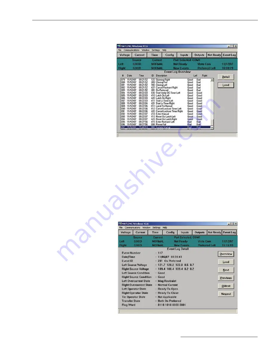
Note that the event log overview lists, for each event, the following:

•  The event number;
•  The date of the event;
•  The time of the event;
•  The event ID number (see the “Appendix” section of Instruction Sheet 515-500 or 

515-600);

•  The event description (the same description indi cated in the “Appendix”  section of 

Instruction Sheet 515-500 or 515-600);

•  The condition of the left source during the event; and
•  The condition of the right source during the event.
•  You can scroll through the event log as desired. For more detail on a particular event, 

highlight that event and click on the Detail button. Or double-click on the event.  The 
following screen will appear.

Following the completion of the download of the Event Log, the Configuration Event 

Log will download during which a dialog box will appear as shown below:

S&C Instruction Sheet 515-506   

25

Summary of Contents for Micro-AT

Page 1: ...ems 23 Uploading the Micro AT Control Event Log 24 Creating an Events File 27 Appendix Setting a Default Configuration 29 S C Micro AT Source Transfer Controls April 28 2014 S C Electric Company Instr...

Page 2: ...this publication must be selected for a specific application The application must be within the ratings furnished for the equipment Warranty The warranty and or obligations described in S C s standar...

Page 3: ...alled on the XP Mode virtual machine Windows 7 64 Bit Windows 7 32 Bit Serial Port USB to Serial Serial Port USB to Serial Windows 7 Does not work Does not work Works correctly Works correctly XP Mode...

Page 4: ...gure 1 Communications card option for Micro AT Source Transfer Controls 4 S C Instruction Sheet 515 506 Micro AT Source Transfer Control User furnished personal computer Communication cable Introducti...

Page 5: ...uction If you do not understand any portion of this instruction sheet and need assistance con tact your nearest S C Sales Office or S C Authorized Distributor Their telephone numbers are listed on S C...

Page 6: ...control connected to the personal computer If you wish to create a configuration s for later down loading proceed to APPENDIX on page 16 Step 1 Place the manual automatic operation selector switch on...

Page 7: ...MAT LINK then highlight and select MATLINK EXE The Matlink application will appear as shown below Step 6 To establish the communication link between your com puter and the Micro AT control a Highligh...

Page 8: ...a changing clock display as shown below indicating that communica tion with the Micro AT control has been established If a problem is encountered in establishing communi cation an appropriate dialog b...

Page 9: ...rom your com puter or from a file If necessary you can use Matlink to view messages explaining why the automatic transfer ready lamp on a Micro AT control isn t lighted And when troubleshooting data l...

Page 10: ...art Programming Instruction Sheet 515 500 or 515 600 for details Normalizing the sources and setting the base voltages must be performed at the Micro AT control These functions cannot be performed usi...

Page 11: ...nnot be changed using Matlink If necessary Preferred Source can be changed at the Micro AT control Bus Type Voltage Sensing Unbalance Install Lockout Option and Supervi sory Control are all fac tory s...

Page 12: ...can be changed using Matlink include Loss of Source Level Return of Source Level Unbalance Level and Overvoltage Level Step 9 If Lockout Option has been factory set for Internal click on the Current...

Page 13: ...Time NOTICE A help screen is available for viewing settings Changing Micro AT Control Settings Step 11 If after checking the factory settings of items listed under the Configuration Voltage Current a...

Page 14: ...Time data window is to be changed proceed to Step 11 e Note that for factory set items which are not field adjustable the alternative settings are shown as Not Changeable c If an item listed in the C...

Page 15: ...le select Return Auto The following screen will appear e If an item listed in the Voltage Current or Time data window is to be changed click on the More button A new window will appear similar to that...

Page 16: ...ent setting The following screen will appear g Enter the desired value The following screen will appear If the operating characteristics and operating parame ters are not to be saved to your computer...

Page 17: ...ter the particular set of operating characteristics and operating parameters that you ve checked and or revised in Change Configuration click on the Save to File button The following screens will appe...

Page 18: ...save to your computer a particular set of operating characteristics and operating parameters by highlighting and selecting File on the menu bar A new pop up menu will appear listing file options as sh...

Page 19: ...screen will appear Enter an appropriate name for the configuration file In both instances two files will be created a binary cfg file and a text formatted txt file A notification prompt will be displa...

Page 20: ...o your computer a particular configuration file that was created in Set tings click on the Load File button The following screen will appear Enter the name of the desired configuration file NOTICE A h...

Page 21: ...e that you ve just downloaded to your computer in Settings click on the Send to AT button After a short delay during which Matlink is transmitting data to the Micro AT control the following screen wil...

Page 22: ...on then a configuration for a pad mounted gear application cannot be entered into the control Viewing the Not Ready List To view messages explaining why the automatic transfer ready lamp on the Micro...

Page 23: ...digital outputs from the con trol can be examined using Matlink To view digital inputs to the Micro AT control click on the Inputs button bar The following screen will appear The true false operating...

Page 24: ...Each such status change referred to as an event is indicated by the illumination of a lamp on the EVENT menu key of the control The last 130 events are stored in memory at any given time in an event l...

Page 25: ...nstruction Sheet 515 500 or 515 600 The condition of the left source during the event and The condition of the right source during the event You can scroll through the event log as desired For more de...

Page 26: ...ring the eventn The right source operator state during the eventn The bus tie operator state during the eventn The transfer controller state during the eventn and The 16 bit flagword for factory diagn...

Page 27: ...ave to your computer an event log that you ve uploaded highlight and select File on the menu bar A pop up menu will appear listing file options as shown below Highlight and select Save Events The foll...

Page 28: ...le Two files will be created a text output log file which can be viewed using an application such as Note pad or Word and a comma delimited csv file which can be viewed using Excel NOTICE A help scree...

Page 29: ...on the computer and run the OS Double click on the MATLINK icon Or open the File Manager Win 3 1 or Windows Explorer Win 95 and select MATLINK then highlight and select MATLINK EXE The Matlink applica...

Page 30: ...inyourMicro ATcon trol s Whenyousubsequentlydownloadtheconfigu rationfile you re creating to a particular Micro AT control Matlink will compare each default value to the corresponding factory set ite...

Page 31: ...a Common high light and select the appropriate drop down setting box A new window will appear listing the alternative settings similar to that shown below In this example select Bus Type Vista Common...

Page 32: ...es of all Not Changeable items click on the OK button The Change Configuration data window will appear similar to that shown below Proceed to Changing Micro AT Control Settings Step 11 c on page 14 Pr...

Reviews: