


18 S&C Instruction Sheet 1041-540
Switch Control Operation
The 5800 Series control software supports 15-kV, 25-kV, and 34.5-kV S&C switches.
The nominal voltage sensor ratios for the line switch(es), with corresponding maximum
voltage levels, are shown in the Table 1.
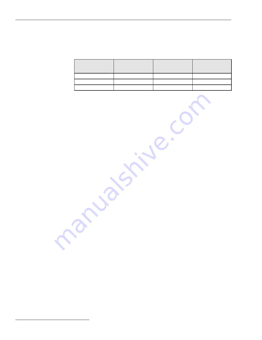
Table 1. Maximum Voltage Levels Supported in S&C Switches
S&C Switch Model
S&C Nominal Voltage
Sensor Ratio
Maximum Phase-to-
Phase Voltage (Delta
Jumper)
Maximum Phase-to-
Ground Voltage (Wye
Jumper)
15 kV
1386:1
20 .0 kV
15 .0 kV
25 kV
2440:1
27 .3 kV
20 .4 kV
34 .5 kV
3389:1
38 .7 kV
29 .0 kV
The Maximum Voltage levels represent the highest voltage measurements supported
by the control software. The maximum voltage levels in Table 1 are based on nominal
sensor ratios. Actual maximum voltages may vary slightly based on the S&C factory-
supplied sensor calibration data (supplied with each switch). (For information on the
physical and electrical specifications for each switch, see the applicable S&C literature.
If support for higher voltage levels is required, contact S&C.)
The third column in Table 1 shows the maximum voltage levels supported for installa-
tions configured for phase-to-phase (delta) voltage reporting. These installations require
the presence of a delta-configured Sensor Conditioning module.
The fourth column in Table 1 shows the maximum voltage levels supported for installa-
tions configured for phase-to-ground (wye) voltage reporting. These installations require
the presence of a wye-configured Sensor Conditioning module.
Accurate voltage reporting requires proper configuration of the setpoints. This includes
entering the actual sensor ratios (as supplied by S&C) for each sensor. It also includes
selection of a voltage-reporting method (phase to phase or phase to neutral) consistent
with customer transformers on the feeder and their associated step-down ratios.
Voltage Sensing for
S&C Switches
The switch control uses a highly accurate, proprietary, zero-crossing detection scheme
(that is not tricked by multiple zero-crossings of noisy or harmonic-contaminated signals)
to measure the phase angles between the voltage and current waveforms on each phase.
The switch control samples the phase angle reading every 0.2 seconds and then
averages eight samples and reports the “1.6-second averaged” value. Phase-angle
measurements are on a 0-360 degree range.
As part of the switch control setup, users can enter
Phase Angle Offset
values to
compensate for both sensor-dependent and installation-dependent phase-angle charac-
teristics.
Phase Angle
Measurements
Overcurrent faults are measured with a combination of peak current detection hardware
for phase faults and true RMS amplitude detection hardware for harmonic-sensitive,
neutral current faults.
To determine whether an overcurrent fault exists, the switch control compares the
sensed current to setpoint values for current level and fault duration. The
Current Level
setpoint value can be specified in 10-amp RMS increments for phase faults and one-amp
RMS increments for ground faults.
The
Fault Duration Time Threshold
value can be specified in 6.25-millisecond
(approximately
1/3
-cycle) increments for phase faults and 50-millisecond increments for
ground faults.
This scheme allows the software to measure fault currents with a scaling appropriate
to the higher amplitude signals encountered with faults and to detect the peaks of narrow
spikes caused by CT saturation that trick many digital sampling schemes.
Overcurrent Fault
& Voltage Loss
Detection


