background image


Installation and Operation Manual 

43 


 3-13 DSC 

This feature requires connection to optional DSC VHF radio.  
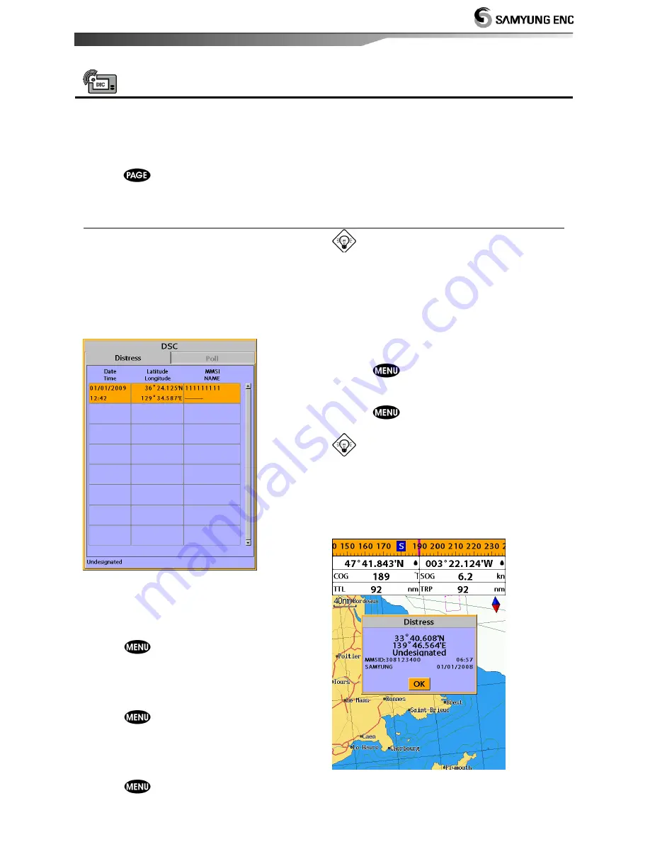
DSC window shows the distress and poll information received from other vessel through DSC 
VHF radio.  
 
To go to the DSC windows: 
1 Press 

, select 

DSC

 icon. 

2 Select one of two tabs

:


Distress

 or 

Poll


3-13-1 distress                                                                                                                    

During a distress situation, a vessel that is 
equipped with a DSC VHF radio and 
connected to GPS has the capability to 
transmit a DSC distress call with GPS 
position. When a compatible VHF radio 
receives a distress call, the distress call 
location is displayed on the screen and it is 
logged into 

DSC


Distress

 window. 


Displaying a distressed vessel in the 
chart window 

1 Highlight a received distress call you want 

to display.  

2 Press 

 and select 

Display

.  

 
Going to the distress position 

1 Highlight a received distress call you want 

to navigate to. 

2 Press 

 and select 

Goto

.  

 
Editing a distress waypoint 

1 Highlight a received distress call you want 

to edit.  

2 Press 

 and select 

Edit Waypoint

.  

3 Change data field and select 

Save

.  

Tip : 

When receiving a Distress call from 

other  vessel,  it  creates  a  distress  waypoint 
automatically.  However,  the  waypoint  you 
edit  in  option  menu  is  a  different  waypoint 
from the distress waypoint.   

 
Deleting a Distress Call 

1  Highlight  a  received  distress  call  you  want 

to delete.  

2 Press 

 and select 

Delete


Deleting all Distress Call


1 Press 

 and select 

Delete all


Tip: 

Even though you delete a DSC call, 

the DSC waypoints still exist. 

 
Distress Message 

When  the  distress  message  is  received,  the 
distress message will be popped up as below.  


Summary of Contents for N560

Page 1: ......

Page 2: ...Installation and Operation Manual 2...

Page 3: ...ity to install and use the unit in a manner that will not cause accidents personal injury or property damage The user of this product is solely responsible for observing safe boating practices Global...

Page 4: ...ust handle Exposure of the display to UV rays may shorten the life of the liquid crystals used in you plotter This limitation is due to the current technology of the LCD display Avoid overheating whic...

Page 5: ...n and off 20 3 2 Brightness night mode and Background 20 3 3 The page window 21 3 4 Chart 23 3 4 1 Chart window 23 3 4 2 Perspective view 23 3 4 3 Latitude and longitude 24 3 4 4 Chart scale 24 3 4 5...

Page 6: ...9 1 Managing a route from the chart window 37 3 9 2 Managing a route from the route window 38 3 10 Satellites 39 3 10 1 Satellite information 39 3 11 Tides 40 3 12 AIS 41 3 12 1 Viewing AIS Vessels 41...

Page 7: ...e Filter 51 4 4 5 Lat Lon d p s 51 4 4 6 Ship speed 51 4 4 7 Magnetic Variation 51 4 5 Track Log Settings 52 4 5 1 Track 52 4 5 2 Logs 52 4 6 Memory Settings 53 4 6 1 Save 53 4 6 2 Load 53 4 6 3 Delet...

Page 8: ...efault 57 4 9 9 Calendar 57 5 INSTALLATION 5 1 Options and Accessories 58 5 2 Connections 59 5 3 Power data cable 59 5 4 Alarm 60 5 5 GPS antenna 61 5 5 1 Internal antenna 61 5 5 2 External antenna 61...

Page 9: ...ION Chart card C MAP SD Card NT MAX NT or NT User card SD Card Waypoints Up to 10 000 with default or user defined alphanumeric names up to eight characters Routes 100 Routes with up to 100 points eac...

Page 10: ...nt down to 0 005 nm in plotter mode COMMUNICATIONS NMEA NMEA 0183 4800 9600 38400 baud NMEA 2000 NMEA 0183 Inputs from compatible instruments DBK DBS DBT DPT GGA GLL GNS GGA GSV HDG HDT MDA MTA MTW MW...

Page 11: ...N560 TK TK TK TK Protection Cover N560 N560 N560 N560 CB CB CB CB User s Manual Eng N560 N560 N560 N560 M M M ME E E E CD ROM Multi language N560 N560 N560 N560 MCD MCD MCD MCD Quick Reference Multi l...

Page 12: ...e unit off 2 Turn the knob to counter clockwise 3 Pull the display unit out Note The chart plotter with internal GPS antenna is designed to be bracket mounting and flush mounting However if you flush...

Page 13: ...o setting menu Show available options of current window zoom in and zoom out to multiple chart level GOTO Start navigating to a destination point such as a MOB waypoint waypoint POWER Turns power on o...

Page 14: ...map between C MAP and S MAP Chart Selection 1 Press and hold 2 Select the system setting icon 3 Select Chart then a chart you prefer S MAP is a pre installed chart but optional C Map Max can be used...

Page 15: ...highlight the data field you want to change then press 4 Select Data type 5 Select a desired data you want to display in the field then press 6 Repeat above steps if necessary Selecting the Data bar s...

Page 16: ...y reading and recognition there is a compass needle at top right side When the compass is displayed COG is always displayed in data field Also when you are navigating to a point COG and BRG is always...

Page 17: ...Split icon on bottom 2 Press or to change the height of the windows if there is only two windows If the unit is displaying more that three windows press or to change the height of the windows Deletin...

Page 18: ...to six favorite windows can be saved Also each favorite display can have data bar and compass Displaying a favorite display 1 Press twice 2 when above window pops up select a desire display you want...

Page 19: ...OB point efficiently MOB will not work if the unit does not have a GPS fix 1 When you press a MOB waypoint is created 2 When is pushed not in the Chart window the screen automatically is changed to Ch...

Page 20: ...s ignition is turned off To turn off you need to turn off the unit manually 3 2 Brightness night mode and Background You can change the screen setting for the display To change settings shortly press...

Page 21: ...The page window Press to show the page window and select a function icon you want to display Note 1 Some function icons require optional units and connected sensors 2 If you press one more time in the...

Page 22: ...Installation and Operation Manual 22 Chart Sonar Highway Data Waypoints Satellite AIS Tides DSC Navtex Engine Faults Routes...

Page 23: ...he cursor A typical waypoint The built in world chart does not show enough detail for navigation When you use the Chart Plotter to navigate always use a chart card which covers the region C C C C MAP...

Page 24: ...position 3 4 4 Chart scale The chart scale change by pressing to show more detail information of chart and by to show wider view of the chart When you press or the scale of chart is display in the ch...

Page 25: ...selected Using C Map Max card allows you to show different kind of symbols and their information on chart plotter display On some objects such as a port you can see a picture of landscape layout To di...

Page 26: ...to one after another The sequence of waypoints leading to the ultimate destination is called a route You can save up to 100 routes and a route may consist of 100 waypoints Start Route Option 1 Press a...

Page 27: ...the cursor to a point which is the end of first leg 4 Repeat 2 3 steps for more legs 5 Press to exit Deleting the last leg 1 Press and select Remove 2 Repeat above step if you want to remove more leg...

Page 28: ...eed and sand show as narrow bands Range of display Color bar The window scrolls from right recent sonar record to left old sonar record 3 5 2 Mode The unit operates in two different modes You can choo...

Page 29: ...w The 50kHz picture appears on the left and the 200kHz picture on the right The display is useful for comparing the same picture with two different frequencies High Frequency 200 kHz Low Frequency 50...

Page 30: ...is ignored by a set value When you use the manual mode and threshold the values of gain and threshold need to be set very carefully In the Gain window you can set for a gain mode and threshold To chan...

Page 31: ...200 kHz sonar history on the right This display is useful for comparing the same history with two different frequencies see section 3 5 10 Split A Scope Display Sonar history and echo strength see se...

Page 32: ...zoom section is adjusted automatically so that the bottom is always displayed in the zoom section To turn Bottom lock on or off press Full Screen zoom Full screen zoom displays only the zoom section...

Page 33: ...o different frequencies 3 5 11 Split A Scope This display shows echoes at each transmission with amplitudes and colors proportional to their intensities on the right of the screen it is useful for est...

Page 34: ...r 3 7 Gauges The Gauges window displays all the information you need during navigation such as water engine fuel related information etc To select the Gauges window press and select Data icon Selectin...

Page 35: ...s and display option 3 Select Save 3 8 2 Moving a waypoint To move a waypoint from the chart window 1 Move the cursor to place it on the waypoint you want to move If you move the cursor on the waypoin...

Page 36: ...final destination of navigation is the waypoint 3 8 5 Find a waypoint To find a waypoint from the chart window Finding waypoints from the chart window is a simplified function 1 Press and select Find...

Page 37: ...press 5 Repeat step 4 to enter more waypoints 6 Once you entered the last waypoint in the route press and select End Editing a waypoint in route while creating a route 1 Move the cursor to the waypoi...

Page 38: ...lect Edit 2 Highlight a leg where you want to insert a waypoint 3 Press and select insert 4 Highlight a waypoint and press 5 Press to exit Editing a route in the chart window 1 In the route list press...

Page 39: ...tion about the GPS satellites and GPS position as below To go to the satellite window press and select Satellite icon The satellite window shows Ship s Coordinates Time received GPS satellites Date re...

Page 40: ...rmation 3 Press to exit Tip The unit only displays the tide information nearest your boat in the tides windows Choosing the date of the tide information 1 In the Tides window Press and select one of t...

Page 41: ...are equipped with AIS unit on the screen To check AIS information place the cursor on the AIS object then AIS information displays at the bottom of window AIS equipped vessel Dangerous Vessel Projecte...

Page 42: ...Installation and Operation Manual 42 AIS Vessel Information 1 AIS Vessel Information 2 AIS Vessel List AIS Vessel Safety message...

Page 43: ...Highlight a received distress call you want to display 2 Press and select Display Going to the distress position 1 Highlight a received distress call you want to navigate to 2 Press and select Goto E...

Page 44: ...a poll you want to display 2 Press and select Display Going to the poll vessel position 1 Highlight a poll you want to go 2 Press and select Goto Edit a distress waypoint 1 Highlight a poll you want...

Page 45: ...t the NAVTEX icon Reloading NAVTEX messages NAVTEX messages need to be loaded from NAVTEX receiver manually Up to 50 messages 1 Press and select Reload all Deleting a message 1 Move the cursor to a me...

Page 46: ...ystem configuration icon 4 1 1 Language Change the language for menus and data screens 4 1 2 Chart Selection Select a chart between S MAP or C MAP chart 4 1 3 Beep volume Select the level of beep soun...

Page 47: ...n and out at scales where cartographic data are not available Mixing levels when the map coverage at the current chart scale does not fill the entire display the GPS chart plotter draws the rest of ma...

Page 48: ...icted Area Turns the displaying of Restricted area on or off Fishing Area Turns the displaying of Fishing Area on or off Sea Cable Turns the displaying of Sea Cable on or off Name Turns the displaying...

Page 49: ...coordinates in WGS84 4 2 7 Map shift Sometimes current position of own ship does not match with the current location on the chart To correct this position error you can apply a map shift Applying a m...

Page 50: ...or off Fish depth labels Turn the fish depth value on or off Fish filter Select a minimum fish size that will be displayed as a fish symbol Fish sensitivity Select the minimum strength fish echo that...

Page 51: ...igation This option is very useful when the boat stops or moves very slowly This option allows you to set a minimum speed at which movement is assumed The value range is from 0 00 to 9 99 4 4 4 Speed...

Page 52: ...rse Display Off Display no track on the chart 1 to 5 select a track number Display a selected track on the chart Record color Select the color of recording track Thickness Select the thickness of reco...

Page 53: ...data type you want to save in the user card then the data will be saved in the user card automatically 1 If you select waypoint for saving data enter the file name and press 2 If you select routes fo...

Page 54: ...eature require an optional AIS receiver To go to the AIS settings 1 Press and hold 2 Select the AIS icon 4 7 1 Display filter There are a couple of methods to filter AIS vessel in this unit as below F...

Page 55: ...roach limit CPA Limit Set the Closet Point of Approach limit Proximity alarm Trigger an alarm when any AIS equipped vessel is within a set proximity radius Proximity radius Set a radius for proximity...

Page 56: ...et value 4 8 4 Temperature Trigger an alarm when the reported temperature from the transducer is same as a set value 4 8 5 Temperature rate Trigger an alarm when the rate of temperature change from th...

Page 57: ...vel at a constant known speed and press or to calibrate the speed Speed filter Set this option when removing effects from waves and wind which affect the speed of boat by averaging Temperature Calibra...

Page 58: ...r DGPS antenna Sonar transducer Fuel sensors DSC VHF radio NMEA 2000 The chart plotter can display engine data and Other instruments The chart plotter can receive data from other instruments and send...

Page 59: ...EMP 5 SONAR 6 SONAR GND 5 2 Connections The GPS chart plotter has connectors that are used to connect to the power supply GPS antenna and to NMEA devices such as VHF s AIS receivers digital instrument...

Page 60: ...nit for auto power as below picture During setup set up Auto power off 5 4 Alarm Wire the chart plotter for any external alarm beepers or lights as below picture The output from the unit to external a...

Page 61: ...e instructions in the manual supplied with the antenna Fit an optional extension cable if required During setup configure the data for the chosen antenna 5 5 3 The antenna using NMEA The chart plotter...

Page 62: ...be connected to other NMEA instruments Set up the optional NMEA instruments as above pictures The chart plotter can receive and display depth paddlewheel boat speed and water temperature from an opti...

Page 63: ...nected to external devices with NMEA2000 and display information such as followings Engines have fuel flow sensors therefore fuel sensors are not required The chart plotter can receive and display win...

Page 64: ...ull speed temperature transducer provide more enhanced performance Contact Samyung ENC for more information Connect the transducer to the chart plotter At the system configuration window set Sonar to...

Page 65: ...he display unit is bracket mounted adjust tilt and rotation for best viewing and hand tighten the knob 3 Insert any required C MAP chart card 4 Enter setup data to set up the chart plotter to your req...

Page 66: ...l costs associated with transducer replacement other than the cost of the transducer itself 3 Routine system checkouts alignment and calibration seatrials unless required by replacement of defective p...

Page 67: ...Installation and Operation Manual 67...

Page 68: ...Installation and Operation Manual 68...

Reviews: