background image


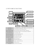
3. PART NAME & FUNCTIONS 


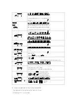
Counter Display 

    Counter Display Counting Values/Timer    Display of the Time progress values 

Setting Display


    Counter Setting Values/Timer setting time indicate 

1/2layer Setting/indicate Lamp


    Check Setting Values and Blink during change of Setting Vales 

Batch Setting/indicate Lamp 

Check Batch Setting Values and    Blink during change of Setting Vales   

Key Lock indicate Lamp 

Key Lock Operate indicate 

OUT1/2 output indicate Lamp 

OUT1/OUT2 Output Operate indicate 

Batch output Display Lamp 

Batch output operate indicate 

Counter Operate indicate Lamp     Blinking during Counter operate 

Timer Operate indicate Lamp 

Blinking during Timer operate 

Reset Button 

    Reset of Counter/Timer 

Batch Button 

    Setting/Check of Batch Counter 

Setting Button 

    Setting of    Counter/Timer Functions 

Cursor Movement Button 

    Setting Position Move 

Increase Button 

    Setting Values Increase/Change 

Counter Display 

1.PS


RST 

BA 

SET


PNT


UP 

Setting Display 

1Layer 

Setting/Lamp 

2 Layer 

Setting/Lamp


Batch Setting Lamp


Lamp 

Key Lock Lamp 

OUT1 output Lamp 

Reset Button 

Batch Button 

OUT2 output Lamp 

Set/Enter Button 

Batch Output Lamp   

2.PS


BA


LOCK


OUT1


OUT2


BA 
OUT


CNT


TMR


Cursor Move Button 

Counter Operation Lamp 

Increase Button 

Timer Operation Lamp 

Summary of Contents for CNT-700

Page 1: ...Caution 1 Please use over M 3 5 width max 7 2m terminal wire for AC power line 2 Do not use without manufacture recommended application it may cause damage of body or broken of product 3 Please preve...

Page 2: ...change of set values Key lock display lamp Key lock operation display OUT1 2 display lamp OUT1 OUT2 operate display Counter operate display lamp Turn on when counter operate Timer operate display lam...

Page 3: ...output operate indicate Counter Operate indicate Lamp Blinking during Counter operate Timer Operate indicate Lamp Blinking during Timer operate Reset Button Reset of Counter Timer Batch Button Setting...

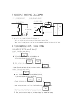
Page 4: ...C AC IN AC IN 100 240VAC 50 60HZ 12VDC BATCH INA INB 100mA 0V RESET INHIBIT RESET 7 6 5 4 3 2 1 9 10 11 12 13 14 8 17 18 16 19 SSR 30VDC 100mA COMMON OUT BATCH OUT T 12VDC BATCH INA INB 100mA 0V RESET...

Page 5: ...ct non voltage input NPN electric contact input connect INA INB 12VDC 0V RESET INHIBIT BATCH RESET 7 6 5 4 3 2 1 INA INB 12VDC 0V RESET INHIBIT BATCH RESET 7 6 5 4 3 2 1 AC IN AC IN 100 240VAC 50 60HZ...

Page 6: ...nal If signal of the INH terminal active the timer become stop timer Time Hold 6 INPUT TERMINAL WIREING DIAGRAM 1 INPUT NON VOLTAGE INPUT NPN 1 NO ELECTRIC CONTACT INPUT 2 ELECTRIC CONTACT INPUT SET T...

Page 7: ...INH Inhibit input during counter operation count input ignore 2 INH Inhibit input during Timer operation timer progress stop 12V SIGNAL INPUT COUNTER TIMER 0V 5 6K Sensor 12V Signal Input PNP Voltage...

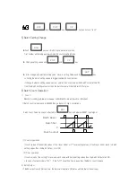
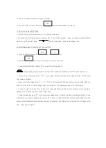
Page 8: ...ode First number will blinking and become setting mode Change setting values use and key After change with wanted setting value save new values push by key 2 2 Layer Display Model Setting push one tim...

Page 9: ...ange with wanted setting value save new values push by key 2 In case of the output mode is FLK Push one time Key during operation mode First number will blinking and become t oFF set vales setting mod...

Page 10: ...Batch Counting Values increase untill Batch reset input is initiated If Batch count values reach to 999999 then go back to 0 like s circulations Batch Count Value s dose not effected for key and exte...

Page 11: ...T output timer oUt t In case of the output mode set as F N count values reach to set values it hold output ON status OUT2 output time items do not show In case of the output mode set as S T D OUT1 OUT...

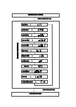
Page 12: ...E COUNT SPEED OUTPUT MODE OUT2 OUT TIME OUT1OUT TIME INPUT LOGIC MIN RESET TIME DECIMAL POINT SCALE SET COUNT MEMORY KEY LOCK COUNTER TIMER SELECT PROGRAMING COUNTER Push 3 second SET key OPERATION MO...

Page 13: ...s Input logic Select input logic voltage non voltage min Reset time external RESET signal input min time interval Unit ms Decimal point Scale setting Scale setting range 0 001 99 999 Scale values K Fa...

Page 14: ...of count input of INA n setting values Preset values In case of INA is L count stop setting INB L H or unlock of count stop INB H L INA Count input stop limitation of the count input of INB INB count...

Page 15: ...A and INBis input from L to H simualtanously It sustain before count input status Incase of Encorder output A B pole connect to couter input INA INB counter mode need set to Ud C mode INA INB H L H L...

Page 16: ...d with OUT2 output R After One shot Time of OUT2 the display values will be recover to Reset Start status The Self sustain output of OUT1 will be OFF after One shot time off OUT2 The One shot output t...

Page 17: ...D ON status sustain only Preset values PRESET1 PRESET2 and Display Values is accord Please use non contact output when you seted count speed to 1kcps 10 TIME RANGE SETTING TIMER TIME RANGE FUNCTION SE...

Page 18: ...Change the setting values use by and key If push the key the cursor move to next step one by one SET UP PNT OPERATION MODE TIMER TIME RANGE UP DOWN MODE OUTPUT MODE OUTPUT TIME INPUT LOGIC INUT SIGNAL...

Page 19: ...e Timer Start 2 In case of INA ON Power ON Time Start Reset OFF Time Start 3 Control Out self sustain operate or One shot operate 4 If repeat INA input the first signal only effective OND 2 Power ON D...

Page 20: ...output by responds time Please set minimum setting time is over 100ms or more FLK 2 Flicker2 Power Hold In case of One shot output 1 Timer start while INA input is ON 2 During INA ON status Power ON S...

Page 21: ...999 0 999999 POWER INHIBIT 9999 99 0 9999 99 0 Up Display Down display 13 ONLY DISPLAY MODE OPERATION 1 Counter In case of Input mode is UP 2 Counter In case of Input mode is DOWN 3 Counter In case of...

Reviews: