17
Maintenanace Procedures cont’d ...
Item
Yes No
Are all nuts and bolts complete and tightened?
Are the blades in good condition with no rusting, dents or nicks? Replace if necessary.
Are the brushes for the electrical motor showing excessive wear (such that there are very deep
grooves on the surface)? Replace if necessary.
Are all bushings, washers, bearings and protective caps in good condition?
Replace immediately if worn as these parts will affect the performance of the unit.
Are the nylon wheels in good condition without any signs of uneven wear? Replace if necessary.
Are each of the hexagonal bolts of even length? Replace if necessary.
Are the safety warning labels and other decals clearly identifi able and legible? If not, ensure
that fresh decals will be re-applied prior to use for operator safety.
A. Inspection
Schedule
The following list aims offer some basic guidelines to performing a detailed inspection BEFORE and AFTER each
use. Certain checks will require some disassembly to perform. Depending on various environmental conditions and
frequency of use, other inspection points may have to be added for each machine.
B.
General Service Procedures
1.Changing the bushings for the SAMURAI Floor Stripper
The bushings and bolts that frame and support the vibrating plate are crucial to the performance of the SAMURAI
Floor Stripper. These parts are also the most common wear and tear parts, due to the vibrating plate design.
In order to inspect and change these parts, the machine must be taken apart in an organized manner.
Before proceeding with any of the following service procedures, please make sure that you have the following
items:
1. Small bottle of liquid soap for lubrication
2. Nut driver included with the SAMURAI Floor Stripper
3. Small bottle of Loctite Blue or other brand of liquid threadlocker
4. Clean, sturdy work area
A.
Disassembling
the
SAMURAI
Floor
Stripper
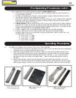
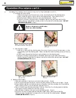
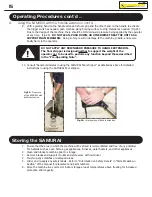
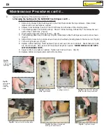
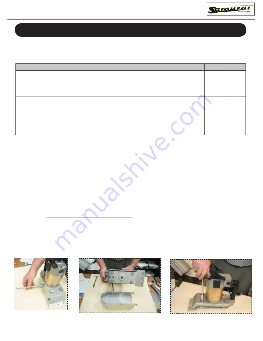
1. Using the nut driver included with your SAMURAI, remove the 6 side bolts from the bottom enclosure.
(Fig.27)
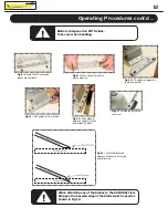
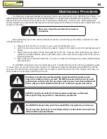
2. Set aside side bolts and remove bottom enclosure. (Fig.28). The vibrating plate is now accessible.
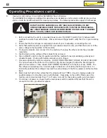
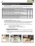
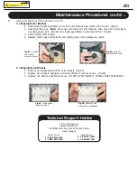
3. Remove and inspect cap nuts, metal washers and rubber bushings from the top enclosure. Replace as
needed. (Fig.29)
Fig.27:
Removing the bottom enclosure.
Fig.28:
Vibrating plate as shown.
Fig.29:
Remove cap nuts and other hardware.

