Baby Lock Pearl BLQF, Assembly Instructions Manual
The Baby Lock Pearl BLQF is a top-of-the-line quilting machine. To help you get started quickly and easily, an Assembly Instructions Manual is available for download, completely free of charge, from our website. This manual provides step-by-step guidance on setting up and operating your machine efficiently.
Share
Download


Reviews:
No comments
Related manuals for Pearl BLQF

S750
Brand: Janome Pages: 41

Panafax UF-8000
Brand: Panasonic Pages: 187
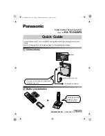
KX-TCD820FX
Brand: Panasonic Pages: 6
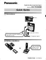
KX-TCD820E
Brand: Panasonic Pages: 6

DP-180
Brand: Panasonic Pages: 65

VX520
Brand: Republic Bank Pages: 18

1243-712/02
Brand: Pfaff Pages: 56

KING COBRA 310-CSA
Brand: U.S. Products Pages: 16

CP335B
Brand: SYSFORM Pages: 28
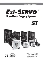
Ezi-SERVO ST
Brand: Fastech Pages: 38

SureBind System One
Brand: GBC Pages: 34

DKS100 SE
Brand: Janome Pages: 61

Truvox International Orbis Compact
Brand: Tacony Pages: 14

6019QC
Brand: Janome Pages: 40

3100 SERIES 569U
Brand: Singer Pages: 22

LT5-H710-1
Brand: Unicorn Pages: 28

Advolution 2710
Brand: Nilfisk-Advance Pages: 60

DDL-5550-7
Brand: JUKI Pages: 12


