background image


User Manual


                96 


features without any limitations. The maximum number of users is 10. They can only use 

features that they have permissions for.   


Right 

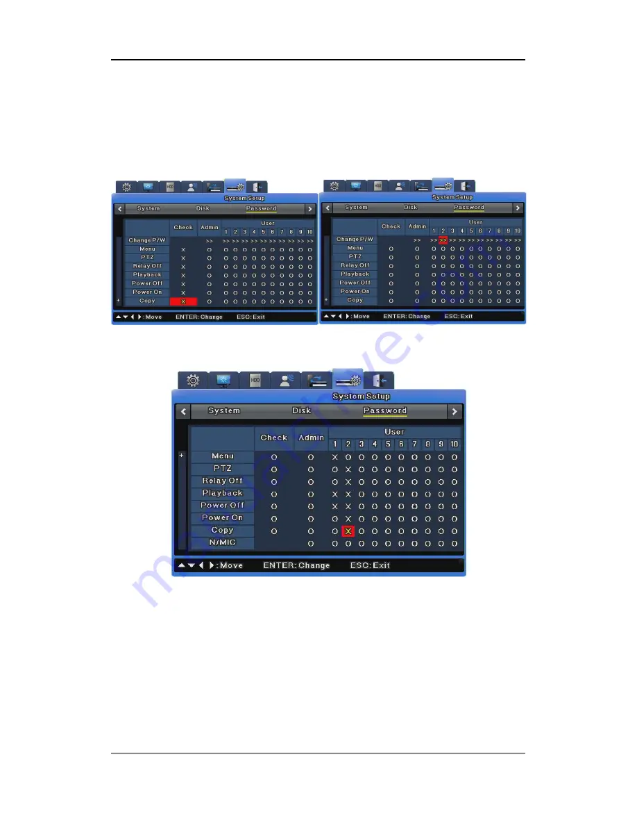
In Right Setup, if Check is set to all X, all users can use all features without any limitations.


If Check is set to all O, each user can use only features for which they have been given 

permissions. 


In the image above, User 1 & 2 can use only “O” function. You can set User 1 to User 10 in the 

same way. 


Admin Password 

The default Admin Password is "11111111" and can be changed. The Admin Password should 

be an 8-digit number. 


User Password 

User 1's password is "11111111", User 2's is "22222222", and similarly for User 3 to User 9. User 

Summary of Contents for SVR-1645

Page 1: ...User Manual 0 ...

Page 2: ...ibility on its behalf Product warranty does not cover cases of accidents negligence alteration misuse or abuse In addition no warranty is offered for any attachments or parts not supplied by the manufacturer The warranty period for this product will be for 3 years from the date of purchase The following cases are not covered by the warranty and payment is required for repairs Malfunction due to ne...

Page 3: ...All installation operations should be performed by the agency you purchased this product from This manual is authored SVR 3200 SVR 1680C SVR 1660C SVR 1645 SVR 960C SVR 945 SVR 480 according to firmware version 1 4 0 Content of this manual can differ by Firmware or Software upgrade and standard and appearance of product is changeable partly without prior notice to users ...

Page 4: ...1 4 SVR 945 20 3 1 5 SVR 480 22 3 2 Rear Part 24 3 2 1 SVR 3200 24 3 2 2 SVR 1680C SVR 1660C SVR 1645 25 3 2 3 SVR 960C 26 3 2 4 SVR 945 27 3 2 5 SVR 480 28 3 3 OSD MENU structure 29 3 4 Function Menu 30 3 5 Factory setting 30 Chapter 4 Monitoring 37 4 1 Default Display 37 4 2 Single Display Full Screen 37 4 3 Multi Display 37 4 4 Auto Sequencing 37 4 4 1 Default System Mode 38 4 4 2 Auto Sequenci...

Page 5: ...reen 44 5 1 2 Playback 44 5 2 Search Mode 45 5 2 1 Time Search 45 5 2 2 Calendar Search 46 5 2 3 Event Search 46 5 2 4 Thumbnail Search 47 5 3 Copy 48 5 3 1 CD DVD 48 5 3 2 RE4 50 5 3 3 AVI 51 Chapter 6 Setup 53 6 1 Record Setup 53 6 2 Time Setup 53 6 2 1 How to Set Time 54 6 3 Camera Setup 55 6 3 1 How to Set a Camera 56 6 4 Monitor Setup 57 6 5 Record Setup 58 6 5 1 Program Setup 59 6 5 2 Manual...

Page 6: ... Disk 93 6 9 3 Security 95 6 10 Exit 97 Chapter 7 Web Viewer 99 7 1 System Requirements 99 7 2 LOGIN 99 7 3 Connection User setup 100 7 4 Supported Browser 101 7 5 Monitor 101 7 5 1 Screen Partition Image Movement 101 7 5 2 Moving Playback 102 7 5 3 Channel On Off 102 7 5 4 Sensor indication 103 7 5 5 Relay operation 103 7 5 6 Microphone use 103 7 5 7 Event Data 104 7 5 8 Video Recording Video Sto...

Page 7: ...ording 107 7 6 3 Print 107 7 6 4 Move to Web Monitor 107 7 6 5 Channel On Off 107 7 6 6 Recording Duration Recording Size Check 108 7 6 7 Calendar Search 108 7 6 8 Playback Toolbar 108 Trouble Shooting 109 Compatible HDD List 111 Compatible Media List 111 Specification 111 Dimensions 116 ...

Page 8: ...use in areas where inflammable substances such as propane gas or gasoline or high amount of dust is present Doing so may cause an explosion or fire Do not touch the power line with a wet hand Doing so may cause an electric shock Do not insert a hand into the opening of the DVD Doing so may cause an injury Make sure conductive materials do not enter the cooling ventilator opening Do not apply exces...

Page 9: ...isk drives may result in abnormal operation Inquire at the agency of purchase before installing additional hard disk drives Product warranty will not cover malfunctions due to additional installation of unapproved hard disk drives This product is a supplementary rather than primary means for preventing fire and theft Our company is not responsible for accidents or damage that may occur Samsung Tec...

Page 10: ...her the retailer where they purchased this product or their local government office for details of where and how they can take this item for environmentally safe recycling Business users should contact their supplier and check the terms and conditions of the purchase contract This product should not be mixed with other commercial wastes for disposal Correct Disposal of Batteries in this Product Ap...

Page 11: ...hannels of audio in real time SVR 3200 1680C 1600 1645 Input 16 channels 4 RCA in rear 12 D SUB This unit is a digital video recording and playback device to record image and video input from 32 16 9 channels to its built in hard disk The buttons on the front of the unit as well as the mouse and GUI allow easy setup and operation The Samsung SVR series of digital video recorders DVRs provide addit...

Page 12: ...VR 3200 Half D1 NTSC 704x240 960fps PAL 704x288 800fps SVR 1680C D1 NTSC 704x480 480fps PAL 704x576 400fps SVR 1660C 1645 CIF NTSC 352x240 480fps PAL 352x288 400fps SVR 960C 945 CIF NTSC 352x240 270fps PAL 352x288 225fps SVR 480 D1 NTSC 704x480 120fps PAL 704x576 100fps Manual and scheduled recording Video signal loss detection Event logs sensors D I O video loss motion detection text Each channel...

Page 13: ... storage Multiple portable data storage media are supported DVD R CD R and USB Refer to the appendix on the back of the manual regarding compatible media types Hard disk expansion device external recording device SVS 5E optional External hard disk expansion is supported with the SVS 5E Available for purchase separately ...

Page 14: ... or 4 section split screen PC playback storage search and DVR control functions via Network Viewer Remote recording search and playback scheduling Supports 10 100Mbps Ethernet xDSL Multiple DVR connections Miscellaneous User friendly GUI and mouse interface Simplified firmware upgrades through USB Visual data recording and backup to USB Supports PTZ control SPEED DOME Coax PRESET Multilingual supp...

Page 15: ...n navigate through the menu and adjust the playback speed and direction Shuttle controls PTZ 4 Channel button Selects channel in live feed or playback 5 AUTO Starts or stops user defined sequences 6 MULTI Changes split screen sections for live video feeds or playback 7 MENU Navigates into the Menu 8 SEARCH Starts Search mode 9 REC button Starts or stops manual recording 10 REC lamp Lit when record...

Page 16: ...o 4 16 PTZ Starts or ends PTZ function 17 USB1 USB2 USB ports for external devices mouse USB memory stick 18 PLAY ENTER Start playback or select an item on the menu 19 REW Navigates or selects in the menu or for playback changes the reverse playback speed 20 FWD Navigates or selects in the menu or for playback changes the forward playback speed 31 PAUSE Navigates or selects in the menu or for play...

Page 17: ...nnel button Selects channel in live feed or playback 5 AUTO Starts or stops user defined sequences 6 MULTI Changes split screen sections for live video feeds or playback 7 MENU Navigates into the Menu 8 SEARCH Starts Search mode 9 REC button Starts or stops manual recording 10 REC lamp Lit when recording HDD lamp Lit when HDD is working NETWORK lamp Lit when network is connected EVENT lamp Lit whe...

Page 18: ...B ports for external devices mouse USB memory stick 18 PLAY ENTER Start playback or select an item on the menu 19 REW Navigates or selects in the menu or for playback changes the reverse playback speed 20 FWD Navigates or selects in the menu or for playback changes the forward playback speed 31 PAUSE Navigates or selects in the menu or for playback pauses live or recorded video 22 STOP Navigates o...

Page 19: ...sections for live video feeds or playback 6 MENU Navigates into the Menu 7 SEARCH Starts Search mode 8 REC button Starts or stops manual recording 9 REC lamp Lit when recording HDD lamp Lit when HDD is working NETWORK lamp Lit when network is connected EVENT lamp Lit when an event is detected COPY lamp Indicates copying operation PLAY lamp Lit when copying 10 Power button Turns on or off the devic...

Page 20: ...t playback or select an item on the menu 18 REW Navigates or selects in the menu or for playback changes the reverse playback speed 19 FWD Navigates or selects in the menu or for playback changes the forward playback speed 20 PAUSE Navigates or selects in the menu or for playback pauses live or recorded video 21 STOP Navigates or selects in the menu or for playback stops playback ...

Page 21: ...e Menu 6 SEARCH Starts Search mode 7 REC button Starts or stops manual recording 8 REC lamp Lit when recording HDD lamp Lit when HDD is working NETWORK lamp Lit when network is connected EVENT lamp Lit when an event is detected COPY lamp Indicates copying operation PLAY lamp Lit when copying 9 Power button Turns on or off the device 10 ESC button The Escape button navigates up the menu tree and cl...

Page 22: ... item on the menu 17 REW Navigates or selects in the menu or for playback changes the reverse playback speed 18 FWD Navigates or selects in the menu or for playback changes the forward playback speed 19 PAUSE Navigates or selects in the menu or for playback pauses live or recorded video 20 STOP Navigates or selects in the menu or for playback stops playback ...

Page 23: ...sections for live video feeds or playback 6 MENU Navigates into the Menu 7 SEARCH Starts Search mode 8 REC button Starts or stops manual recording 9 REC lamp Lit when recording HDD lamp Lit when HDD is working NETWORK lamp Lit when network is connected EVENT lamp Lit when an event is detected COPY lamp Indicates copying operation PLAY lamp Lit when copying 10 Power button Turns on or off the devic...

Page 24: ...rt playback or select an item on the menu 18 REW Navigates or selects in the menu or for playback changes the reverse playback speed 19 FWD Navigates or selects in the menu or for playback changes the forward playback speed 20 PAUSE Navigates or selects in the menu or for playback pauses live or recorded video 21 STOP Navigates or selects in the menu or for playback stops playback ...

Page 25: ...nal between DVR and external device 7 ETHERNET Ethernet port for network connections RJ 45 8 STORAGE External storage connection port Function not supported in the current version 9 eSATA Connection terminal for external eSATA HDD or HDD for backups 10 VGA OUTPUT Output port for PC monitor 11 Serial Port Terminal Block RS 232C 485 422 Connection terminal for expanded controller speed dome camera e...

Page 26: ...put 5 AUDIO IN RCA RCA audio jack for RCA input 6 AUDIO OUT Audio jack for speaker output 7 GROUND Ground terminal between DVR and external device 8 ETHERNET Ethernet port for network connections RJ 45 9 STORAGE External storage connection port Function not supported in the current version 10 eSATA Connection terminal for external eSATA HDD or HDD for backups 11 VGA OUTPUT Output port for PC monit...

Page 27: ...on terminal for camera BNC output loop 5 MONITOR 1 2 Connection terminal for monitor BNC output 6 AUDIO IN RCA RCA audio jack for RCA input 7 AUDIO OUT Audio jack for speaker output 8 ETHERNET Ethernet port for network connections RJ 45 9 eSATA Connection terminal for external eSATA HDD or HDD for backups 10 VGA OUTPUT Output port for PC monitor 11 Serial Port D Sub RS 232C D SUB connector 12 Seri...

Page 28: ...A input 5 AUDIO OUT Audio jack for speaker output 6 ETHERNET Ethernet port for network connections RJ 45 7 eSATA Connection terminal for external eSATA HDD or HDD for backups 8 VGA OUTPUT Output port for PC monitor 9 Serial Port D Sub RS 232C D SUB connector 10 Serial Port Terminal Block RS 232C 485 422 Connection terminal for expanded controller speed dome camera etc 11 RELAY OUT Connection termi...

Page 29: ... for monitor BNC output 5 AUDIO IN RCA RCA audio jack for RCA input 6 AUDIO OUT Audio jack for speaker output 7 ETHERNET Ethernet port for network connections RJ 45 8 eSATA Connection terminal for external eSATA HDD or HDD fo backups 9 Serial Port D Sub RS 232C D SUB connector 10 VGA OUTPUT Output port for PC monitor 11 Serial Port Terminal Block RS 485 422 Connection terminal for expanded control...

Page 30: ... 29 Refer to detailed description for installation use from Install Manual 3 3 OSD MENU structure The menu structure is as shown below For detailed instructions for configuration please refer to Chapter 4 5 and 6 ...

Page 31: ...een mode The function menu structure is as shown below 3 5 Factory setting To restore the unit back to its factory settings go to System System Restore Factory Setting A pop up window saying Warning The system will be reset Continue with restoring factory default will appear Select Yes and press Enter to restore the factory default settings Factory Default Quick Setup Record Mode Manual Event Sche...

Page 32: ... Number 1 is set to Channel 1 and Number 2 is set to Channel 2 in order Dwell Time 5 sec Multi Display 4E Channels 1 3 5 and 7 VGA Mode 800x600 56Hz On Screen Display Select All Record Setup Record Record Mode Schedule Event Schedule Not Set All Event Duration Before 1 sec After 1 sec Repeat Record Mode On Warning Level 45 Record Data Retention Off Playback Deinterlace On Audio Audio Channel Ch1 A...

Page 33: ...ormal Event Source Deselect All System Event Source Deselect All Normal Event MD Ch1 MD Sensitivity 2 Area Set All Sensor N O Text Recording Off Sync Text With Ch1 Device Manual Seek Header Off Header 1 header1 Header 2 header2 Delimiter 0D0A Timeout ms 1000 Lines 20 Preset Channel Number Ch1 Preset Not Set D I O D I O Output Output Type Sensor Network Network Type Ethernet DHCP Off ...

Page 34: ...000 Bandwidth Limit Mbps 0 0 DDNS Interval Off Server www samsungipolis com ID None Password None Status Not Registered NTP Sync With NTP Off NTP Mode Client NTP Server Loc Public NTP Local Server IP 0 0 0 0 Interval 1 hour Remote Remote Keyboard ID Com1 Remote Controller ID All Remote Configuration Setup Enable Remote Relay Enable Serial Com1 PTZ Ch1 System Setup System Language English Key Buzze...

Page 35: ...ger Disk Status Security Change P W Default value Menu Check X Admin and User O PTZ Check X Admin and User O Relay Off Check X Admin and User O Playback Check X Admin and User O Power Off Check X Admin and User O Power On Check X Admin and User O Copy Check X Admin and User O N MIC Check None Admin and User O Exit Exit Save Do not save ...

Page 36: ... 10 Q4 Half 20 Q5 Half 10 Q4 Half 20 Q5 M Half 10 Q4 Half 15 Q5 Half 10 Q4 Half 15 Q5 N Half 5 Q4 Half 10 Q5 Half 5 Q4 Half 10 Q5 O Half 5 Q4 Half 10 Q4 Half 5 Q4 Half 10 Q4 P Half 3 Q4 Half 5 Q4 Half 3 Q4 Half 5 Q4 Q Half 1 Q4 Half 3 Q4 Half 1 Q4 Half 3 Q4 R Half 0 Q4 Half 7 Q5 Half 0 Q4 Half 7 Q5 S CIF 30 Q5 CIF 30 Q5 CIF 30 Q5 CIF 30 Q5 T CIF 20 Q5 CIF 30 Q5 CIF 20 Q5 CIF 30 Q5 U CIF 20 Q4 CIF ...

Page 37: ... Q4 Half 20 Q5 Half 20 Q4 Half 20 Q5 M Half 20 Q4 Half 15 Q5 Half 20 Q4 Half 15 Q5 N Half 15 Q4 Half 20 Q5 Half 15 Q4 Half 20 Q5 O Half 15 Q4 Half 20 Q4 Half 15 Q4 Half 20 Q4 P Half 4 Q4 Half 15 Q4 Half 4 Q4 Half 15 Q4 Q Half 1 Q4 Half 3 Q4 Half 1 Q4 Half 3 Q4 R Half 0 Q4 Half 7 Q5 Half 0 Q4 Half 7 Q5 S CIF 30 Q5 CIF 30 Q5 CIF 30 Q5 CIF 30 Q5 T CIF 20 Q5 CIF 30 Q5 CIF 20 Q5 CIF 30 Q5 U CIF 20 Q4 C...

Page 38: ...assword for the unit has been set the password input dialog is displayed 4 2 Single Display Full Screen Press a channel button or left click Press the MULTI button or left click once again to go back to the split screen 4 3 Multi Display To watch multiple channels simultaneously press the MULTI button or the button from the Function menu and click split mode Each press of the MULTI button toggles ...

Page 39: ...tup on the OSD menu Go to the Monitor submenu under Display Setup and press the Enter button or left click Select Dwell Time and set a value between 1 and 60 seconds When this is set to Off auto sequencing will not work Auto sequencing mode can be enabled by pressing the AUTO button in all split modes To exit auto sequencing mode press the AUTO button once again 4 4 2 Auto Sequencing Mode Press th...

Page 40: ...hannel split screen 4 4 Event Screen You can set an event screen to automatically pop up The Event Screen can be set for each monitor To set the dwell time for each event popup select a monitor and set the dwell time for the monitor When events occur in several channels simultaneously the screen automatically splits into that number of channels For example if events occur in 3 channels event image...

Page 41: ...tton select the button and press the Enter button or left click When the button is selected the default location is the center of the screen When an image is zoomed in on it can be moved 18 levels horizontally and 12 levels vertically Use the navigation keys to move the image To return to the previous screen select the button and then press the Enter button or left click 4 6 Live Video Pause You c...

Page 42: ...oard models are as shown below Model Maker SDZ160 330 Samsung SPD Keyboard SCC3000 Samsung SRX 100B SAMSUNG TECHWIN BOSCH AutoDome TC8560X 4 BOSCH PELCO P PELCO D PELCO Honeywell 755 655 HRX 2000 ScanDome2 HONEYWELL Sony EVI D3x SONY VT VPT 4x VT AD SpeedDome AD SungJin SJ372R1 SUNGJIN Samsung SCC641 SAMSUNG ELECTRONICS Panasonic WV CS850 PANASONIC LG GAC PT2 LG Keyboard KBD300A WGI SPD1800 2600 W...

Page 43: ...oring Select Zoom Focus in PTZ mode Use the navigation keys on the front or the mouse wheel to use Zoom and Focus 4 7 3 Load Preset This menu item is used to go to a preset location in the real time monitoring mode Use the up or down arrow key or the mouse wheel to select a preset number Select Load and then press the Enter button or click 4 7 4 Save Preset This menu item is for setting a new pres...

Page 44: ...ect Off and then press the Enter button or click 4 7 7 Menu This is used to enter the console menu of the connected PTZ device The console menu can be set with the navigation keys and the Enter button on the front After settings are done press the ESC button or the PTZ button on the front to exit the console menu available only with the Samsung SPD protocol ...

Page 45: ...ton plays recorded videos from the last playback timestamp PAUSE Pause video playback When using a mouse click the button in the Function menu STOP Stop video playback When using a mouse click the button in the Function menu FWD Each press of this button changes the playback speed in the order of x1 x2 x4 x8 x16 x32 x64 x1 2 x1 x2 and x4 Pressing the FWD button while viewing a live feed plays the ...

Page 46: ...play the video in reverse at 1 2x speed 5 2 Search Mode This menu item is used to search by time or log to play data at a specific time Search mode includes Time Calendar Event and Thumbnail To go into search mode press the Search button on the front or click the Search button on the Function menu 5 2 1 Time Search Enter a desired date and time and select Search to go to the video at the specified...

Page 47: ...nter button You can use the mouse wheel to search by time Time Select a time period and press the Enter button to start playback When using a mouse select the time and use the mouse wheel to play the video at the specified time 5 2 3 Event Search You can specify a time period and search all channels some channels all events motion detection or sensors Use the up or down arrow key on the front to c...

Page 48: ...s the Enter button and use the up or down arrow key to change the value When using a mouse click an item and use the mouse wheel to change the value Event Channel Select a channel For the SVR 3200 Ch1 Ch32 are available For the SVR 1680C 1660C 1645 Ch1 Ch16 are available For the SVR 960C 945 Ch1 Ch9 are available For the SVR 480 Ch1 Ch4 are available Event Type Select an event type You can select ...

Page 49: ...Press the Func button or use the mouse wheel to return to the search window Select Video Click a video thumbnail and play it from the specified time Press the Enter button or click to play the video Changing the I frame duration may produce results different from your expectation from Thumbnail Search 5 3 Copy This menu item is used to copy a recorded video There are three types of copy CD DVD RE4...

Page 50: ...can select some or all of the 16 channels Select the channel field and press the Enter button or use the mouse wheel to select a channel From Enter the start date and time for copying Use the up or down arrow key or the mouse wheel to set the value To Enter the final date and time for copying Use the up or down arrow key or the mouse wheel to set the value Select Disk Select the media to copy Sele...

Page 51: ...el list as shown below SVR 3200 SVR 1680C 1660C 1645 SVR 960C 945 SVR 480 Type Select RE4 Use the up or down arrow key or the mouse wheel to select it Channel Select the channel field and press the Enter button or use the mouse wheel to pop up the channel list Select Channel You can select some or all of the channels Select a channel on the channel list and press the Enter button or left click Fro...

Page 52: ... HDD storage Type Select AVI Use the up or down arrow key or the mouse wheel to select it Channel Select a channel Use the up or down arrow key or the mouse wheel to select it From Enter the start date and time for copying Use the left or right arrow key to move between the items and use the up or down arrow key to change the time and date When using a mouse left click an item and use the wheel to...

Page 53: ...e Start button and press the Enter button or left click FAT32 Format Format unformatted USB storage devices and HDDs in FAT32 before copying Select the FAT32 Format button and press the Enter button or left click If the copied file does not play on a PC install the unified codec pack ...

Page 54: ...describes recording modes For more information on recording refer to the following sections 6 2 Time Setup You need to set the system time before setting recording Setting the time based on your location is very important for the protection of recorded data It is Recording Event Recording Schedule Recording Manual Recording Emergency Recording ...

Page 55: ...t or right arrow key on the front or the mouse wheel to select your time zone Each press of the arrow keys changes the time zone To go to the previous menu press the ESC button on the front or right click This is the same for all OSD menus Daylight Saving This menu is linked to Time Zone This menu is enabled only when a location with daylight saving is selected in Time Zone Daylight saving locatio...

Page 56: ...cted to the unit You can use the camera setup menu to adjust Title Status Color AGC Brightness Contrast for each of the connected cameras The set values apply to monitoring and search in the same way For more information on each menu item refer to the following sections NTSC and PAL cameras cannot be used for the unit at the same time For example you cannot connect NTSC cameras to 1CH to 5CH while...

Page 57: ...ing the character input window appears The character input window may differ depending on the menu but the character input method is the same Use the navigation buttons to input characters When using a mouse click a character Press the navigation buttons to select characters After selecting characters press the Enter button to input them To delete characters press the Í button to move back To inse...

Page 58: ...mera Press the Enter button and use the left or right arrow key or the mouse wheel to select Enable or Disable Brightness Contrast You can adjust the brightness and contrast of a video Press the Enter button and use the left or right arrow key or the mouse wheel to select a value between 9 and 9 6 4 Monitor Setup This menu is used to set related items when displaying a video on the monitor Monitor...

Page 59: ...se the Enter button or the mouse wheel to open the window and press the Enter button or click to select a channel Then press the ESC button or right click SVR 480 does not support to set multi display VGA Mode Three VGA modes are provided for VGA monitors The available modes are 800x600 1024x768 and 1280x1024 On Screen Display This determines what information is displayed for live video feeds or v...

Page 60: ...cur simultaneously in more than two channels the recording frame rate may be automatically adjusted Program Under the Program menu a total of 26 programs labeled from A to Z are available for you to define with the recording resolution and quality for each channel For more information about the setting values of the Program menu please refer to section 3 5 Ch Channel Indicates a channel number R R...

Page 61: ...us of CIF 30fps recording capacity You can use the surplus CIF 352x240 30fps to increase another channel s resolution to Half D1 704x240 30fps remember from above that CIF x 2 Half D1 Setting a channel s frame rate to 0fps in the Program settings Surplus CIF 30fps cannot be used to increase another channel s resolution because the 0fps channel still uses at least 2 to 3 recording frames per second...

Page 62: ...multiple channels and the Event Recording settings value exceeds the DVR s maximum recording performance the Normal Recording settings value is retained and the channels with events drop their Event Recording frame rates settings to record the events The SVR 1680C provides D1 30 compressed frames for all channels it can record programs at a manually selected resolution and frame rate at all times ...

Page 63: ... LED on the front will flicker Also S is displayed to show that currently all channels are recorded as scheduled 6 5 2 Manual Schedule Recording Setup You can switch between Manual and Schedule Recording by changing the recording mode Both Manual and Schedule Recording enable you to choose a program to record The resolution frame rate and quality may vary depending on the selected program ...

Page 64: ...ule Event Schedule Recording Settings Schedule Recording records video automatically at a scheduled time according to the chosen program settings Set the recording mode to Schedule Event then select a program for a scheduled date and time When selecting a program the default settings value of the program is displayed for you to confirm You can select one or more programs from among the 26 availabl...

Page 65: ...he Delete button If you click on the Delete button before selecting INDEX then the content of INDEX that was selected previously will be deleted first After that the content in the highest INDEX will be deleted and then others INDEX will be deleted in the increasing order of INDEX Editing Method Select the INDEX to be edited and then change DAY PROGRAM and HOUR on your own If all the INDEX fields ...

Page 66: ...for playback only the 2 day recording is available for playback Playback Deinterlace This turns playback deinterlace on or off This is available only when the recording resolution is set to Full D1 If this is set to On imaging shaking decreases while Full D1 video is paused 6 5 3 Evnet Record Setup This menu item is used to record video based on events To use Event Recording select a resolution fr...

Page 67: ...Schedule Event 2 In the Program settings change the frame rate of Normal Recording to 0 and of vent Recording to the desired rate 3 Set an Event Check to activate the recording Event Check Settings This menu item sets times for event recording and has the options of Always Disable and Timezone The Always option always detects events while the Timezone option uses events only for specified hours Wh...

Page 68: ...click on the Delete button If you click on the Delete button before selecting INDEX then the content of INDEX that was selected previously will be deleted first After that the content in the highest INDEX will be deleted and then others INDEX will be deleted in the increasing order of INDEX Editing Method Select the INDEX to be edited and then change DAY and HOUR on your own If all the INDEX field...

Page 69: ...ideo feeds If Yes is selected audio is outputted even for playback Audio Gain This menu is used to adjust audio volume up or down Sync Video Channel This menu is used to determine which channel the input audio is linked to for output This is available only for recording Audio output for live video feeds is described in Audio Mixing If Sync Video Channel is set to 5 for Channel 1 audio the audio in...

Page 70: ...ss of channel selection If specific audio is selected only the specified channel is outputted regardless of the channel selection 6 7 General Event Setup This menu is used to set events that you want to use Motion Detection Setup This menu is used to save events occurring through motion detection for each channel SVR 480 does not support Digital I O ...

Page 71: ...en each channel is set individually Area can be set to Set All Unset All or User Defined User Defined User Defined is only available when each channel is set individually It is used to set an area where you want to detect motion intensely It allows you to set a user defined motion detection area You can select one or more motion detection areas out of the squares on the 22x15 grid The default sett...

Page 72: ...y incoming text data is structured In other words all data has its start and end points and the header is data that is always inserted to indicate the start point Therefore by defining a header here the DVR can recognize from the header that it is the start point of the data Two headers can be set and detected because one device can send various types of data to external receivers Delimiter The de...

Page 73: ... so it is recommended to contact the manufacturer before installation 6 7 2 Preset This menu is used to activate the presets specified in the PTZ based on sensor input Specify a preset with PTZ attached to each channel Select a channel in the preset menu and select an event for the preset You can choose sensor MD or text for an event and 16 presets can be set ...

Page 74: ...y even one channel emergency recording will operate When they are set to output if sensor input is received it will operate In Digital I O Setup if you set one of the 12 Digital I O to Input set Input Type to Emergency and turn Digital I O on the emergency recording will operate The macro set in the event recording is used for the recording The recording will continue based on the value set in Rec...

Page 75: ...ation Action Duration is used to maintain an action for a specified time when relay or buzzer is set If E Mail is set e mails are sent in specified time intervals Normal Event Source You can set Normal Event Source to 16 Sensors 16 MDs 16 Video Losses and Text Emergency SVR 480 does not support Digital I O thus it does not display Emergency on select mode ...

Page 76: ...utput For e mail address enter an e mail address for a message recipient The address format is xxxx xxxxxx xxx However only Roman alphabet letters and numbers are allowed Sender Address Sender Address is set when e mail is used for output The address format is xxxx xxxxxx xxx You do not have to enter an e mail address In general use an address that identifies the e mail as being sent from a specif...

Page 77: ...e event channel along with the event information including the sensor movement detection and object disappearance For a System event log the system sends only the event information because the channel pairing option is not available 6 8 Network This sets network information when connecting the DVR to a network Type ...

Page 78: ...dress to the DVR DHCP is used on a LAN with a DHCP server installed Generally small and large LANs have DHCP servers while small LANs use Network Address Translation NAT from a hub or router IP Addr IP Address is used for communication between the DVR and Network Manager and is also used when Webviewer accesses the DVR This is available only when Net Mask and Gateway are set Net Mask Net Mask spec...

Page 79: ...en necessary 6 8 1 xDSL If the DVR is connected to xDSL and uses PPPoE set Type to xDSL and specify a user ID and password You must use the user ID and password given when you subscribed to the xDSL service User ID Password If the DVR is connected to xDSL you must specify a user ID and password Status This shows the connection status of the DVR 6 8 2 DDNS If the DVR is connected to a cable modem o...

Page 80: ...er a dynamic IP address to a DDNS follow the instructions shown below DDNS Registration procedure 1 Sign up at iPOLiS homepage The homepage URL is www samsungipolis com Accept the terms and conditions SIGN UP page check ID availability 2 Register the product after sign up Log on to iPOLiS website ...

Page 81: ...User Manual 80 Product List If you didn t register products there are no list Product Registration Check ID availability Information regarding the registered products may be reviewed from the list ...

Page 82: ...e illustration shown below Set DDNS to On and input the DDNS address in DDNS SERVER DOMAIN NAME The default value is www samsungipolis com For ID and PW use the user ID domain and password used in iPOLiS product registration process This concludes the necessary configurations to the DVR for DDNS connection 4 The connection status of product can be checked on the product list ...

Page 83: ...ce the product has been registered its ID domain may not be changed When the product s ID needs to be changed the product s registration must be reset Register the product again with the new ID To register a fixed IP address to a DDNS follow the instructions shown below Interval To maintain continuous registration status a registration cycle must be assigned from Interval ...

Page 84: ...e registered The address of the SWR is www samsungipolis com ID Use the ID for the DDNS login Password Use the password for the DDNS login Status The DVR s registration status is indicated Not Registered means that the DVR is not registered to the DDNS Date Time OK means that the DVR has been registered to the DDNS 6 8 3 NTP Network Time Protocol NTP synchronizes time between devices on network On...

Page 85: ...e IP of the NTP server Enter either the IP of an NTP server on the local network or the IP of a DVR with its NTP mode set to Server Interval This menu is used to set the synchronization interval When NTP Mode is set to Client Sync With NTP must be set to On 6 8 4 Remote DVR ID This sets the address of the keyboard when operating all DVR functions with the controller buttons The default value is 1 ...

Page 86: ...Enable is set SNM Configuration is available for setup If Disable is set SNM Configuration is unavailable for setup Remote Relay Remote Relay is used to determine whether to use the Relay On Off function on the SNM monitor If Enable is set all four relays can be controlled remotely If Disable is set remote control is unavailable with the SNM Configuration 6 8 4 1 Serial Port A total of four serial...

Page 87: ...ext option supports only Com1 RS 232 make sure to select Com1 on the Serial Port menu Device Select Text Interface Select RS 232 Baud rate Parity Stop Bit Data Bit Enter the same settings as the ones for the selected TP device 6 8 4 1 2 Transparent To use a transparent device please follow the instructions below ...

Page 88: ...lable for SVR 480 Baud rate Parity Stop Bit Data Bit Enter the same settings as the ones for the selected Transparent device 6 8 4 1 3 Keyboard To set up a keyboard select Keyboard for the Device option and then select a keyboard model Device Select Keyboard Keyboard Select a desired keyboard model Interface ...

Page 89: ...PTZ Select PTZ To control the PTZ operation via serial port select PTZ in the Device options and then set up a serial port refer to 6 8 4 2 2 PTZ Serial To control the PTZ operation via coax protocol you do not need to set up this option Refer to 6 8 4 2 PTZ Device Select a connected PTZ device 6 8 4 2 PTZ Two PTZ control methods are available via serial port and coax protocol ...

Page 90: ...in addition to the basic PTZ functions To use this option a PTZ device must be embedded with a coax standard or extended protocol SVR 3200 SVR 1645 SVR 945 SVR 480 does not support coaxial function Type Select Coax Protocol Select Pelco or Pelco Extended according to the coax protocol type of Pelco camera AD Dome does not support menu control Presets or AUX when setup with a coax protocol Idle Tim...

Page 91: ... To use RS 232 select Com3 For RS 422 or 485 select Com2 or 4 Baud rate Parity Stop Bit Data Bit Enter the same settings as the ones for the PTZ device Idle Time Activate or disable PTZ Home and set up a standby duration for the device before moving to PTZ home For more information on cameras supporting PTZ and how to set them up refer to 4 8 PTZ Use 6 9 System Setup ...

Page 92: ...onfiguration This saves the DVR setting to a USB storage device Firmware Update Save the Update Firmware for USB to USB storage and connect it to the DVR Select Firmware Update from System Setup and press the Enter button When a message prompting you to update appears select Yes and press the Enter button After a while a buzzer beeps and the unit reboots The Update Firmware for USB is provided in ...

Page 93: ...reboot the unit is displayed Select Yes to reboot the unit DVR Alias This sets a DVR alias System Log The system logs various events including changing menu settings turning the power on or off changing the time zone turning HDD on or off using the Copy function and when system events occur You can check log details with the icon by pressing the Enter button or scrolling the mouse wheel ...

Page 94: ...e This is used to set the time zone date format and time for the DVR Daylight Saving needs to be set depending upon the region I Frame Duration An I frame duration is the interval between I frames and is measured by the video frame rate For video recordings with less motion I frame duration enhances the video quality You should only set I frame duration settings to anything other than Auto if you ...

Page 95: ...s HDD status bad blocks size enabled disabled etc Type Displays disk locations and types Int A Internal A HDD Int B Internal B HDD Ext External HDD Model Displays HDD models Bad Block Displays HDDs with bad blocks 0 is displayed when there are no problems Nothing is displayed for HDDs not in use ...

Page 96: ...it to Enabled Yes Select Yes to delete the previous data stored in the HDD and change it to Enabled Yes To change HDD to No Enabled Select Yes and press the Enter button or use the mouse wheel to open the notice window with the following message Warning Do you want to remove the disk Select Yes to open the The disk has been removed message and change the HDD to Enabled No The HDD is now unused Sel...

Page 97: ...mitations If Check is set to all O each user can use only features for which they have been given permissions In the image above User 1 2 can use only O function You can set User 1 to User 10 in the same way Admin Password The default Admin Password is 11111111 and can be changed The Admin Password should be an 8 digit number User Password User 1 s password is 11111111 User 2 s is 22222222 and sim...

Page 98: ... character input window to enter a new password Click the Change button to save it Clicking the Change button displays a popup confirmation window that prompts you to change password Click Yes The password has been changed Permissions Using permission restricted features requires a password check Execute a command to open the password input window Select a user and enter his her password Now the f...

Page 99: ... 98 Save This saves all settings and exits to the live screen Select Yes to save all settings and exit or select No to exit without saving any settings Do not save This is used to exit without saving any settings ...

Page 100: ... Display Resolution 1280 x 1024 with 32bit color or higher HDD 1GB or higher OS Windows XP Professional Window Vista Business Others DirectX 9 0 or higher 7 2 LOGIN Use the IP address and port assigned to the product to access the Web Viewer Log in page The URL to access the page will be similar to http 192 168 1 100 4000 If the port value has been changed from the default value of 4000 use the ch...

Page 101: ...guration Tool Up to 1 administrator and 10 regular user IDs and passwords may be issued For security purposes the administrator and regular passwords must be distinct Uncheck the usage box of unused user accounts as well The illustration above displays Network Manager Configuration Tool after user IDs and passwords have been changed ...

Page 102: ... allow Web Viewer s functions to work as intended Please close all programs related to Network Manager before installing Web Viewer Failure to do so may result in malfunction 7 5 Monitor Once provided with the correct ID and password combination Web Viewer will automatically move to the monitoring page The monitoring page is used to watch live visual feed or to perform other functions allowed with...

Page 103: ...corresponding to Ch 3 over Ch 6 to switch their places 7 5 2 Moving Playback Click the Playback button shown above to move to the playback page 7 5 3 Channel On Off Channel On Off buttons are located to the left of the page Click the channels to toggle between On and Off The default value for all channels is On The above illustration displays the result of toggling Ch 8 and 9 off When turned off b...

Page 104: ... s Relay can be set to On or Off Clicking a relay button will set the corresponding relay to On and change the button s color from blue to orange Deactivated relay buttons are relays not supported by the DVR model Relay actions require a specific authority level Consult the manual on how to configure relay authority level 7 5 6 Microphone use Microphone usage may be set to On or Off The default va...

Page 105: ... video may be recorded in this manner If a Quick Recording operation is executed the duration of the recording will be displayed on the visual Selecting Rec Stop while recording will conclude the recording operation A dialogue window regarding the file location will be prompted and the user may save the file in any desired directory The recording will save as a re4 file which can be played in NETW...

Page 106: ...a to change its position faster Zoom Focus Control Placing the cursor at the left and right sides of the screen will reveal the zoom and focus slide bars A camera unit supporting Area Zoom In will also support the Zoom Zero button Use the slide bar to the left to zoom in and out and the right slide bar to control focus PTZ Home If a preset position is configured right click during PTZ mode and sel...

Page 107: ...e screen will disconnect the visual connection and fade to black To reconnect the channel click the off channel button again 7 6 Playback Recorded data can be reviewed in the playback mode Only users with HDD access may use this mode The playback mode uses 16 Partition screens and supports searches by time calendar and cycle Also paused streams may be printed or saved as bmp image files Detailed e...

Page 108: ...logue window will pop up A brief memo on the image can be saved with it Click OK to prompt save location window 7 6 3 Print Printing a channel is similar to capturing a frame Click the channel to print and click Print Type the relevant memo and click OK to print the image The print will contain the printing date channel name recording date event and memo 7 6 4 Move to Web Monitor To move to Web Mo...

Page 109: ...eframe Clicking Go To will display the timeframe of 24 hours beginning from the date and time specified above at the bottom left Click 24h to adjust the timeframe 7 6 8 Playback Toolbar Displays the recording duration Shifts through the time frame by an interval set by 5 From left to right Move back 1 frame Play backward Pause Play and Move forward 1 frame Sets the standard video speed Click the b...

Page 110: ...mera s power supply z Check the camera s input status z Check the DVR s input port z Check the Activity setting under the Screen menu z Check the Covert setting under the Monitor menu 4 The video won t record z Check for the HDD connection status from Disk Manager z Check the Recording settings 5 The recordings won t play z Check the Recording settings z Check the button activity 6 Images are too ...

Page 111: ...not run properly 10 Cases to contact purchasing agency If the following cases occur immediately cease the product operation shut off the power supply and take the console to the purchasing agency for repair z The product malfunctions during operation Ex Strange noise smell smoke etc z The power cable or the connector has been damaged z The product has been flooded z The product has been spilled on...

Page 112: ...ion Exhortation 16X Imation Exhortation 16X Sony Exhortation 16X Sony Exhortation 16X Specification Item Description Display Video Inputs SVR 3200 32 composite video 0 5 2 Vpp 75 ohm automatic termination SVR 1680C 1660C 1645 16 composite video 0 5 2 Vpp 75 ohm automatic termination SVR 960C 945 9 composite video 0 5 2 Vpp 75 ohm automatic termination SVR 480 4 composite video 0 5 2 Vpp 75 ohm aut...

Page 113: ... 352x240 Record Rate PAL SVR 3200 400fps 704x576 800fps 704x288 800fps 352x288 SVR 1680C 400fps 704x576 400fps 704x288 400fps 352x288 SVR 1660C 1645 100fps 704x576 200fps 704x288 400fps 352x288 SVR 960C 945 100fps 704x576 200fps 704x288 225fps 352x288 SVR 480 100fps 704x576 100fps 704x288 100fps 352x288 Mode Manual Schedule Event Emergency Overwrite modes Continuous Pre Event Up to 5 sec Post Even...

Page 114: ...DVD R CD R USB Back up 2 External USB Ports USB 2 0 File Format Back up BMP AVI Proprietary format JPG Exclusive viewer Security Password Protection 10 User Level Data Authentication Watermark Interface Monitors VGA Analog RGB 800x600 1024x768 1280x1024 resolution Main Composite BNC 1 Vp p 75 ohm Multi screen Menu Playback Sub Composite Monitor2 4 SVR 3200 1680C Menu Event Pop up Covert Display Sw...

Page 115: ...1 port Application Support ATM POS Mouse Remote Controller Dome Protocols Supported PTZ cameras Samsung Techwin Pelco D Pelco P Pelco Coaxitron Panasonic Bosch SEC General Electrical Input Voltage 100 to 240 VAC 10 50 60 Hz Auto ranging Power consumption Max 65 W with 1x HDD Max 88 W with 2x HDD Max 90 W with 4x HDD Environmental Operating Temperature 5 C to 40 C 32 F to 104 F Operating Humidity 0...

Page 116: ...User Manual 115 Portuguese Russian Turkish Japanese Czech Serbian Swedish Rumanian Danish Chinese Korean Taiwanese ...

Page 117: ...User Manual 116 Dimensions SVR 3200 SVR 1680C SVR 1660C SVR 1645 ...

Page 118: ...User Manual 117 SVR 960C ...

Page 119: ...User Manual 118 SVR 945 ...

Page 120: ...User Manual 119 SVR 480 ...

Page 121: ...User Manual 120 ...

Page 122: ...User Manual 121 ...

Reviews: