Circuit Operating Descriptions
7-33
RF and frequency synthesized tuning system
General description : The receiving circuit consists of both ANT input and output circuits, channel selection cir-
cuit, PIF circuit and SIF circuit. The receiving circuit selects a desired broadcast signal from TV signals induced on
an antenna and sends stable video and audio signals to their respective processing circuits. The output signals
from the video and audio circuits are converted into a conventional TV signal modulated for channel 3 or channel
4 by an RF modulator so that the signal can be received by conventional TV receivers.
(2) Tuner modulator block
As explained, this model is designed in one package to contain a RF MODULATOR BLOCK, TUNER BLOCK
AND IF DEMODULATOR BLOCK. Its size is greatly reduced and other noise interference can be minimized to
make performance high.
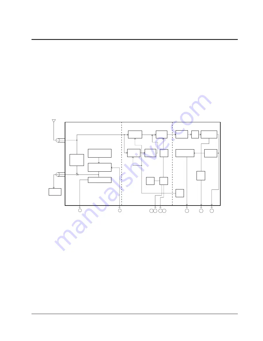
Fig. 7-30 Tuner/demodulator Block Diagram
11
3
5
12
21
23
24
ANT INPUT
(MODULATOR SECTION)
(TUNER SECTION)
(IF SECTION)
ANT OUT
Off
through
SW
RF Carrier
OSC
VHF
RF AMP
UHF
RF AMP
UHF
Mixer
VHF
OSC
FM
Detector
SIF
Filter
UHF
OSC
PLL
IC
AGC
AFT
Mixer
IC
SAW
Filter
IF
AMP
Video
Detector
Video
Modulator
FM Modulator
TV SET
AUDIO IN
VIDEO IN
SCL SDA
AUDIO OUT
AFT OUT
VIDEO OUT
2
6
7-7 TM
(1) Outline
Summary of Contents for SV-DVD40
Page 82: ...Circuit Operating Descriptions 7 7 Fig 7 12 Block Diagram ...
Page 116: ...Circuit Operating Descriptions 7 41 3 Block Diagram Fig 7 38 LA70100M Block Diagram ...
Page 141: ...VCR Deck Operating Description 8 12 Samsung Electronics Fig 8 14 Mecha Timing Chart ...
Page 156: ...Samsung Electronics 11 1 11 Wiring Diagram ...
Page 158: ...Schematic Diagrams 12 2 Samsung Electronics 6 1 S M P S ...
Page 159: ...Schematic Diagrams Samsung Electronics 12 3 6 2 Power Drive ...
Page 160: ...Schematic Diagrams 12 4 Samsung Electronics DT701 6 3 Display Function ...
Page 161: ...Schematic Diagrams Samsung Electronics 12 5 6 4 System Control Servo ...
Page 162: ...Schematic Diagrams 12 6 Samsung Electronics 6 5 A V ...
Page 163: ...Schematic Diagrams Samsung Electronics 12 7 6 6 Hi Fi ...
Page 164: ...Schematic Diagrams 12 8 Samsung Electronics 6 7 A2 NICAM ...
Page 165: ...Schematic Diagrams Samsung Electronics 12 9 6 8 SECAM Option ...
Page 166: ...Schematic Diagrams 12 10 Samsung Electronics 6 9 OSD VPS PDC ...
Page 167: ...Schematic Diagrams Samsung Electronics 12 11 6 10 TM ...
Page 168: ...Schematic Diagrams 12 12 Samsung Electronics 6 11 Input Output ...
Page 169: ...Schematic Diagrams Samsung Electronics 12 13 6 12 DVD AV Decoder ...
Page 170: ...Schematic Diagrams 12 14 Samsung Electronics 6 13 DVD Servo ...
Page 171: ...Schematic Diagrams Samsung Electronics 12 15 6 14 DVD Audio Video ...


