VCR Deck Operating Description
8-24
Samsung Electronics
<RPS mode>
(1) When the [REW] button is pressed in the playback mode, the mechanism enters the RPS mode.
The cam slider is in the position IV (playback mode), the cylinder motor is rotating, and the capstan motor is
rotating in the forward direction.
(2) IC601 controls the audio circuit to actuate the audio mute operation.
(3) IC601 controls Capstan Motor Drive IC to make the loading motor rotate in the reverse direction.
After 180ms the loading motor stops for 250ms. During the mode shift operation, the mechanism rotates the
capstan motor in the forward direction for a constant time so that the tape is not slackened.
(4) When the cam slider reaches the position “c” (loading motor stoped for 250ms), the capstan motor is rotated in
the reverse direction for a constant time, and the idle gear is swung toward the S reel disc side.
Then, the loading motor rotates in reverse direction and shifts to the position III (RPS mode).
When the cam slider reaches the position III (RPS mode), the loading motor stops.
The mechanism status is as follows :
1) The No.9 guide is loaded.
2) The tension post is separated from the tape.
3) The T soft brake is turned on.
The cpastan motor rotates in the reverse direction at 7 times for SP, 21 times for SLP to feed the tape in the
REW direction, respectively. At the same time, the idle gear transmits the rotation to the S reel disc and
the S reel disc takes up the tape by the clutch mechanism.
(5) The recording speed data identified by IC601 is displayed on the Led module.
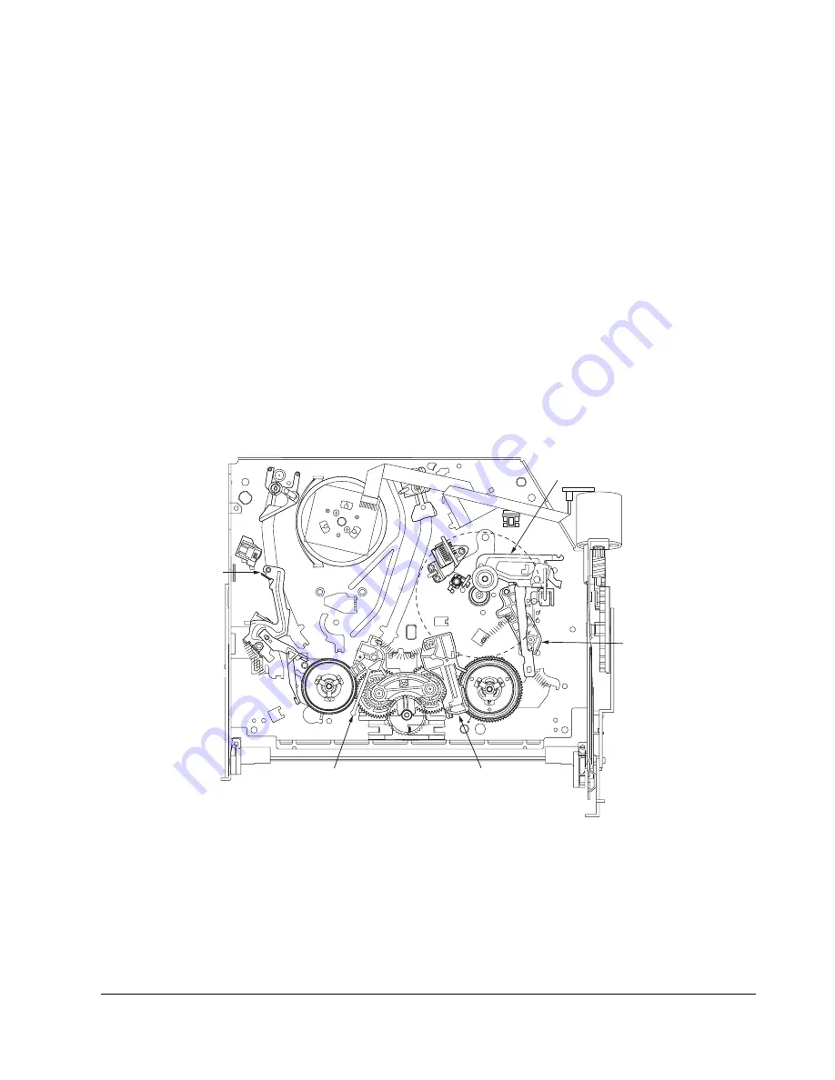
T brake (RPS brake)
S brake (OFF)
Tension lever (OFF)
Pinch assembly (ON)
No. 9 guide lever (ON)
Fig. 8-28 RPS Mode (Position III)
Summary of Contents for SV-DVD40
Page 82: ...Circuit Operating Descriptions 7 7 Fig 7 12 Block Diagram ...
Page 116: ...Circuit Operating Descriptions 7 41 3 Block Diagram Fig 7 38 LA70100M Block Diagram ...
Page 141: ...VCR Deck Operating Description 8 12 Samsung Electronics Fig 8 14 Mecha Timing Chart ...
Page 156: ...Samsung Electronics 11 1 11 Wiring Diagram ...
Page 158: ...Schematic Diagrams 12 2 Samsung Electronics 6 1 S M P S ...
Page 159: ...Schematic Diagrams Samsung Electronics 12 3 6 2 Power Drive ...
Page 160: ...Schematic Diagrams 12 4 Samsung Electronics DT701 6 3 Display Function ...
Page 161: ...Schematic Diagrams Samsung Electronics 12 5 6 4 System Control Servo ...
Page 162: ...Schematic Diagrams 12 6 Samsung Electronics 6 5 A V ...
Page 163: ...Schematic Diagrams Samsung Electronics 12 7 6 6 Hi Fi ...
Page 164: ...Schematic Diagrams 12 8 Samsung Electronics 6 7 A2 NICAM ...
Page 165: ...Schematic Diagrams Samsung Electronics 12 9 6 8 SECAM Option ...
Page 166: ...Schematic Diagrams 12 10 Samsung Electronics 6 9 OSD VPS PDC ...
Page 167: ...Schematic Diagrams Samsung Electronics 12 11 6 10 TM ...
Page 168: ...Schematic Diagrams 12 12 Samsung Electronics 6 11 Input Output ...
Page 169: ...Schematic Diagrams Samsung Electronics 12 13 6 12 DVD AV Decoder ...
Page 170: ...Schematic Diagrams 12 14 Samsung Electronics 6 13 DVD Servo ...
Page 171: ...Schematic Diagrams Samsung Electronics 12 15 6 14 DVD Audio Video ...


