background image

CAMERA MENU 

Press the “SETUP” ICON on left below to control the menu of the
selected camera.

Using the direction key and the enter key, control the CAMERA
MENU.
Press the EXIT ICON to clear the camera menu.

• When you control the menu of SAMSUNG DOME CAMERA, you can

use the joystick as a direction or enter key by moving it or after pressing
the AF button of it.

DVR control

Please refer to the manual of each DVR since DVR’s functions are
varied depending on the model.
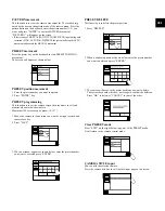
DVR selection

1. Press the DVR key.
2. Enter the DVR number (0~255) you want by using the number

keys and press ENTER.

3. Varied window will appear depending on the DVR model.

Ex) SHR-4080

• If you press the DVR key in the Camera Control or MUX Control mode,

the DVR Input Box will be displayed in the screen as follows. Then, select
DVR in the same manner as above.

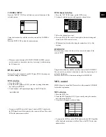
DVR channel selection

1. Press the “CH” ICON below on the DVR screen.
2. A channel selection screen will appear as shown below.

3. Select the channel you want.
4. Press the EXIT ICON on the lower right to finish selecting and

return to the DVR control screen

• DVR channel can be selected by using the number keys (0~9) of the 

keyboard.

DVR MENU

Press the setup icon on the lower left to control the menu of the
selected DVR.

Using the direction key and the enter key, control the DVR MENU.
You can use the joystick as a direction or enter key by moving it or
using the AF button.
Press the EXIT ICON to finish controlling the DVR MENU.

MUX control

SDM-160 can be controlled. Please refer to the manual of SDM-160
for detailed explanation.

MUX selection

1. Press the MUX key.
2. Enter the MUX number (0~255) you want by using the number

keys and press ENTER.

3. A window will appear as shown below.

• If you press the MUX key in the DVR Control mode, the MUX Input Box

will be displayed in the screen as follows. Then, select MUX in the same
manner as above.

GB-11

Summary of Contents for SSC-2000

Page 1: ...System Keyboard SSC 2000 User s Manual GB F D ES I R P ...

Page 2: ...defeat the safety purpose of the polarized or grounding type plus A polarized plug has two blades with one wider than the other A grounding type plug has two blades and a third grounding prong The wide blade or the third prong are provided for your safety If the provided plug does not fit into your outlet consult an electrician for replacement of the obsolete outlet 10 Protect the power cord from ...

Page 3: ...onnecting PC by RS 232 gb 7 Connecting Other System Keyboard gb 7 Basic System Diagram of SSC 2000 gb 7 Chapter 4 Instructions gb 8 Log in gb 8 Camera control gb 8 DVR control gb 11 MUX control gb 11 Chapter 5 MENU setup gb 12 MAIN MENU gb 12 KEYBOARD SETUP gb 12 RS 485 COMMUNICATION SETUP gb 12 RS 232 COMMUNICATION SETUP gb 13 CHANGE PASSWORD gb 14 CHECK PASSWORD gb 14 REGISTER NEW OPERATER gb 14...

Page 4: ...ation of the unit and the composition of wiring are very important in prop erly operating the system When equipment is placed too close or if ventilation is not properly done system may not work properly and maintenance of the system may be difficult In order to prevent sys tem failure and to reduce system shut down by outside environmental factors air circulation in the system operating room and ...

Page 5: ... it from being deviated when you connect it with the main body Chapter 3 Connecting with Other Equipment You can use the SSC 2000 system key board with a camera DVR MULTIPLEXER and the other equipments This chapter describes how to connect each equipment Connecting RS 485 Device Connect RS 485 Device through the port in the back of SSC 2000 You are able to install and control the camera DVR and mu...

Page 6: ...licable to the Version 3 1 over Connect with SSC 2000 by using the RS 485 port on the back of SHR 4080 In case of connecting with Half Duplex Connect the Tx of SHR 4080 RS 485 port with the Tx of SSC 2000 Connect the Tx of SHR 4080 RS 485 port with the Tx of SSC 2000 In case of connecting with Full Duplex Connect the Tx of SHR 4080 RS 485 port with the Rx of SSC 2000 Connect the Tx of SHR 4080 RS ...

Page 7: ...ifferent with the SSC 1000 in communication method 1 In case of connecting with Half Duplex Connect the Tx of SSC 2000 port with the Tx of another SSC 2000 Connect the Tx of SSC 2000 RS 485 port with the Tx of another SSC 2000 2 In case of connecting with Full Duplex Connect the Tx of SSC 2000 with the Rx of another SSC 2000 Connect the Tx of SSC 2000 with the Rx of another SSC 2000 Connect the Rx...

Page 8: ...ess the touch panel key or move the joystick joy shuttle and then the screen before the sleep mode is displayed again Camera control Selecting a camera 1 Press CAM key The camera display part of the screen will be as follows 2 Enter the camera number 0 255 you want by using the number key and press ENTER Selecting a monitor This function is to choose a monitor displaying the image of the cam era 1...

Page 9: ...on is to set the camera screen the user wants to call and monitor whenever he she wants to Maximum 128 screens can be preset 0 127 1 Move the camera to the position you want by using a joystick and camera lens key 2 Press SAVE 3 When a window appears as shown below enter the preset number you want to save and press ENTER PRESET DELETE This function is to delete the preset position 1 Press DELETE 2...

Page 10: ...e camera number display part Move to the connected device When you press DVR 000 on the connection information screen DVR 000 will be selected and the screen will be changed into the DVR control mode When you press MUX 000 on the connection information screen MUX 000 will be selected and the screen will be changed into the MUX control mode Enter the number of the connected DVR 1 Press the DVR key ...

Page 11: ...nnel selection 1 Press the CH ICON below on the DVR screen 2 A channel selection screen will appear as shown below 3 Select the channel you want 4 Press the EXIT ICON on the lower right to finish selecting and return to the DVR control screen DVR channel can be selected by using the number keys 0 9 of the keyboard DVR MENU Press the setup icon on the lower left to control the menu of the selected ...

Page 12: ...ayed on the screen when you complete the log in process Press the item you want to control on the main menu Press the EXIT ICON in the main menu to return to the camera con trol mode If the CHECK PASSWORD item is set Off in the keyboard setup press the MENU button MAIN MENU screen will directly appear without the log in process If you press the menu button while the OPERATOR s LEVEL is the MANAGER...

Page 13: ...ollows 4800 9600 19200 38400 Among these 4 kinds of BAUD RATE select one BAUD RATE DUPLEX You can set the duplex mode of system keyboard Press DUPLEX and then the following window pops up FULL DUPLEX HALF DUPLEX Select one of the two duplex Press the exit icon on the lower left to finish RS 485 COMMUNICATION SETUP control and return to the KEYBOARD SETUP screen RS 232 COMMUNICATION SETUP The defau...

Page 14: ...will be displayed on the screen You have to start again from entering the operator s number CHECK PASSWORD If it is set On a window will appear to ask the operator no and password when you entering the Menu screen If it is set Off you can directly enter the Menu mode The system has been set On on shipment REGISTER NEW OPERATER This function is to add a new user of the keyboard New Operator No Ente...

Page 15: ...system An informing message will appear if there is already data stored in the system keyboard Press OK to start downloading Press Cancel or the EXIT ICON to return to the KEYBOARD SETUP screen DOWNLOAD process screen A download process screen will appear as shown below when you press OK on the down load check screen A message will appear when downloading is completed CAMERA DATA UPLOAD This funct...

Page 16: ...t a language among these languages Factory Default Setup Resets all of the menu values to the default value Press OK to start the default setting The system will start again when the FACTORY DEFAULT SETUP is completed Chapter 6 OPERATOR LEVEL There are 3 levels of user who can be registered as a user including Admin Manager Operator Admin is the highest level The range and limit to the usage of va...

Page 17: ...VERSE PLAY REVERSE PLAY FF RW POWER DC12V 600mA POWER CONSUMPTION BELOW 3W DIMENSIONS WxHxD NET 490 x 197x 282 PACKAGE 496 x 206x 288 WEIGHT kg NET 1 36Kg PACKAGE 2 6Kg Chapter 8 Q A The system keyboard communication is not worked Check the RS 485 communication line Check the address setup of system keyboard Refer to RS 485 COMMUNICATION SETUP GB 12 of Chapter 5 Menu setting for the method of addr...

Page 18: ...GB 18 ...

Reviews: