


GB-4
B. Camera movement key
- PRESET
- PATTERN
- SCAN
- AUTO PAN
C. Alarm release key
D. Joystick controller (UP/DOWN/LEFT/DOWN/AF/ZOOM)
The Pan/Tilt connected with Samsung Dome Camera or Receiver Unit
is moved to UP/DOWN/LEFT/RIGHT. Press the button on the top of
Joystick to control the Auto Focus. And use for the zoom control by
turning to the clockwise or counterclockwise. The function of UP/
DOWN/LEFT/RIGHT keys is controlled in the menu screen of the
connected controller. Press the button of the top to execute ENTER
motion.
E. Camera lens key
- IRIS control (IRIS CLOSE/OPEN)
- FOCUS control (FOCUS NEAR/FAR)
- ZOOM control (ZOOM TELE/WIDE)
F. MENU key
This key is to go into the menu mode for the setup of various devices.
G. Device select key (MON/CAM/MUX/DVR)
This key is to select Camera, Monitor, DVR, MUX Number, or oth-
ers.
H. Number key (0~9), ENTER key, CLEAR key
This key is to select Camera, Monitor, DVR, MUX Number, Preset,
Pattern Number, or others.
I. DVR control key (SEQUENCE, MODE)
- SEQUENCE : Executes the SEQUENCE function of DVR.
- MODE : Executes the partition screen selection function of DVR.
J. Jog shuttle
- JOG : Is in use for Forward / Reverse Frame search in the playback
mode of DVR.
- Shuttle : Executes the Play / Reverse Play / FF / REW functions in
the playback mode of DVR.
K. DVR play key
- PLAY/PAUSE
- STOP
- FAST FORWARD
- REWIND
- RECORD
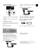
Back side
L. DC 12V IN
DC 12V power input terminal.
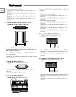
M. RS-485
For RS-485 communication, it will be connected to the RS-485 termi-
nals of other system keyboards or controlling devices such as cam-
eras, DVR, and MUX.
N. RS-232
Connection port to adjust the system key board in a factory.
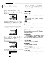
Chapter 2. Installation
Installation Environment Setup
The following information is prepared for safe installation of the unit.
This unit can be placed on a flat table or installed in the rack. It
should not be used vertically or skew, but horizontally. The location
of the unit and the composition of wiring are very important in prop-
erly operating the system. When equipment is placed too close or if
ventilation is not properly done, system may not work properly, and
maintenance of the system may be difficult. In order to prevent sys-
tem failure and to reduce system shut-down by outside environmental
factors, air circulation in the system operating room, and the cover of
the unit must be fixed. Do not open the cover voluntarily because
high voltage within the unit may cause electric shock.
PHYSICAL & ENVIRONMENTAL
• Operating Temperature : 0 °C to 40 °C
• Temperature : -20 °C to 60 °C
• Operating Humidity : 20% to 85% (RH)
• Maintenance Humidity : 20% to 95% (RH)
• Power Supply : 12 VDC, 600mA ( )
• Power Consumption : less than 3W
Caution
When system is operated, input voltage range must be within 10% of
nominal voltage, and power consent should be grounded. Heating devices
such as hair dryer, iron, refrigerator should not be used together. For safe
power supply, AVR (Automatic Voltage Regulator) is recommended.
The connector linked to this equipment can affect EMI, so it is recom-
mended to coil the CORE-FERRITE for use.
Cautions for Installation
• Be sure to turn the unit off before installing.
• Avoid shock or vibration since they may cause unit malfunction.
• Keep away from magnets, radio or TV to avoid magnetic damage.
• During or after installing the unit, be sure to maintain the area around the
unit clean.
• Place the unit on a flat surface and maintain temperature properly. Allow
15 cm of clearance between the rear panel and the wall.
• Be careful not to drop any conductive materials into the hole for ventilation
• When replacing built-in fuse, be sure to turn the power off, and unplug the
unit.
• Avoid locating the unit where direct sunlight will fall, and maintain it cool.
Keep tools and equipment away from people so that they would not be
hurt.
• If ignoring smoke or smell while using the unit, fire or electric shock may
occur. In this case, turn the power switch off immediately, and consult pro-
fessionals in the closest service center.


