background image

Index

Soldering point.

Male connector.

Female connector.

M/F faston connector.

Test point.

Supply voltage.

Logic supply ground.

Analog supply ground.

Chassis ground.

Earth ground.

Flag joined with one or more flags

GENERALMUSIC S.p.A. Sales Division: 47842 S.Giovanni in Marignano (RN) ITALY - Via delle Rose, 12 - tel. 0541/959511 - fax 0541/957404
GENERALMUSIC on the NET: http://www.generalmusic.com

Opening, Keyboard Disassembling Instructions and Autotest Procedure

2

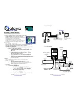
Assembly & Wiring Connections

3

Block Diagram, Midi & Controls I/O and Keyboard Int. Pcb Layouts 

5

Cpu & Sound Generator Map

6

Power Amplifier & Supply Schematic, Adjustment Table

7

Midi & Controls I/O, Keyboard Interface & L/R Contact Schematics

8

Controls Panel, Trackball & Dc-Ac Converter Schematics

9

Cpu & Sound Generator Schematic (Part 1/2)

10

Cpu & Sound Generator Schematic (Part 2/2)

11

A/V & Vocal Processor Schematic

12

Power Amplifier & Supply, Phones & Trackball Pcb Layouts

13

Spare Part List

14

Controls Panel Pcb Layout & Reverse Layout

4

A/V & Vocal Processor Pcb Layouts

Cpu & Sound Generator Pcb Layout

15

16

SERVICE  MANUAL

 CODE: 270215 

6

8

Warnings

with the same signal name inscribed.

Address

ATTENTION

Observe precautions when handling electrostatic sensitive devices.

Notice

Service must be carried out by qualified personnel only.Any tampering carried out by unqualified personnel during the guarantee period
will forfeit the right to guarantee.
For a correct operation of the instrument, after having switched off, be careful to wait at least 3 seconds before switching on again.
To improve the device's specifications, the schematic diagrams may be subject to change without prior notice.
All components marked by this symbol have special safety characteristics, when replacing any of these components use only
manufacturer's specified parts.
The (µ) micro symbol of capacitance value is substituted by U.
The (

) omega symbol of resistance value is substituted by E. 

The electrolytic capacitors are 25Vdc rated voltage unless otherwise specified.
All resistors are 1/8

 unless otherwise specified.

All switches shown in the "OFF" position. All DC voltages measured to ground with a voltmeter 20KOhm/V.


Assembly & Layout

Timing Table

17

18

2nd Edition

Summary of Contents for WK 6

Page 1: ...al Processor Pcb Layouts Cpu Sound Generator Pcb Layout 15 16 SERVICE MANUAL CODE 270215 6 8 Warnings with the same signal name inscribed Address ATTENTION Observe precautions when handling electrostatic sensitive devices Notice Service must be carried out by qualified personnel only Any tampering carried out by unqualified personnel during the guarantee period will forfeit the right to guarantee ...

Page 2: ...ng the 1MHz clock signal on pin 1 of COMPUTER socket 4 Controls Panel Press in order GENERAL SYSTEM INFO F2 and F8 to enter in the TEST page confirm the operation pressing ENTER select PANEL TEST A and subsequently push all the buttons on the control panel to check their correct operation verify the TRACKBALL joystick operation checking its value variation from 0 to 127 with 64 at the center for P...

Page 3: ... 20 9 6 7 17 LCD ADJ 21 15 18 19 For descriptions and codes see the correspondance on reference column REF in the PART LIST above 11 12 10 Y 23 X 14 GENERALMUSIC S p A ITALY 27 4 1 5 AFT ADJ 8 22 2 26 3 28 13 24 25 ...

Page 4: ...S DOCUMENT WITHOUT ALL RIGHTS ARE RESERVED NO COPIES GENERALMUSIC S p A ITALY PART DWG DISK REV PCB Falconi Boccato Boccato 550143 30 06 98 64 LAYOUT 1 1 48 58 62 63 61 60 59 56 57 55 54 47 42 6 10 35 34 10 44 40 30 49 52 39 36 50 38 46 41 53 31 36 32 51 45 18 43 37 33 35 ...

Page 5: ...5 5 5 5 5 ...

Page 6: ... ALL RIGHTS ARE RESERVED NO COPIES OR REPRODUCE THIS DOCUMENT WITHOUT WRITTEN CONSENT BY GENERALMUSIC MIDI CONTROLS I O BOARD PCB LAYOUT KEYBOARD INTERFACE BOARD PCB LAYOUT DRW APP CKD WRITTEN CONSENT BY GENERALMUSIC OR REPRODUCE THIS DOCUMENT WITHOUT ALL RIGHTS ARE RESERVED NO COPIES GENERALMUSIC S p A ITALY PART DWG DISK REV PCB Pannelli N Riccobelli G Boccato 550145 14 04 98 64 WK6 8 BLOCK DIAG...

Page 7: ...7 7 7 7 7 ...

Page 8: ... 8 8 8 8 8 ...

Page 9: ...LAYOUT GENERALMUSIC S p A Italy SCHEMATIC DIAGRAM WK6 WK8 Phones Tackball and Power Amp Supply Board Pcb Layouts DRW BOCCATO APP PANNELLI REV 25 05 98 DISK 4 PART 1 1 CKD RICCOBELLI ALL RIGHTS ARE RESERVED NO COPIES ORREPRODUCETHISDOCUMENTWITHOUT WRITTEN CONSENT BY GENERALMUSIC DWG 315085 1 315095 096 ...

Page 10: ... 10 10 10 10 10 ...

Page 11: ...oard Pcb Layout and Reverse Layout DRW BOCCATO APP PANNELLI REV 25 05 98 DISK 4 PART 1 1 CKD RICCOBELLI DWG 315084 ALL RIGHTS ARE RESERVED NO COPIES ORREPRODUCETHISDOCUMENTWITHOUT WRITTEN CONSENT BY GENERALMUSIC CONTROLS PANEL BOARD PCB REVERSE LAYOUT CONTROLS PANEL BOARD PCB LAYOUT ...

Page 12: ... 12 12 12 12 12 ...

Page 13: ...13 13 13 13 13 ...

Page 14: ... WK6 WK8 Cpu Sound Generator Board Pcb Layout DRW BOCCATO APP PANNELLI REV 25 05 98 DISK 4 PART 1 1 CKD RICCOBELLI DWG 315083 ALL RIGHTS ARE RESERVED NO COPIES ORREPRODUCETHISDOCUMENTWITHOUT WRITTEN CONSENT BY GENERALMUSIC CPU SOUND GENERATOR BOARD PCB LAYOUT ...

Page 15: ...et the jumper as follow 1 2 A if Buffer modules are installed 2 3 B if SIMM DRAM modules are installed note the buffer modules are supplied with A V Vocal processor kit if neither buffer or Simm modules are installed J1 position is ininfluent CN4 CN12 to A V Vocal Processor Board CN3 to MIDI I O Board CN2 to Controls Panel Board CN1 or CN17 to Lcd Display depend by organ model CN6 to Outputs or Am...

Page 16: ...WK6 WK8 Audio Video Interface Board Pcb Layout DRW BOCCATO APP PANNELLI REV 25 05 98 DISK 4 PART 1 1 CKD RICCOBELLI ALL RIGHTS ARE RESERVED NO COPIES ORREPRODUCETHISDOCUMENTWITHOUT WRITTEN CONSENT BY GENERALMUSIC A V VOCAL PROCESSOR BOARD PCB LAYOUT DWG 315109 ...

Page 17: ...TER IC6 A AD1877 8 16 IC1 B 74AC138 4 3 AR9 A 33E X4 2 1 AR9 B 33E X4 6 5 AR9 C 33E X4 2 1 AR16 A 33E X4 R7 1K 4 3 AR16 B 33E X4 8 7 AR16 D 33E X4 C49 330P 8 7 AR3 D 33E X4 5 6 IC20 C 74HC04 2 3 1 IC3 A 74HC125D R90 33E C39 100N 9 8 10 IC3 C 74HC125D D3 BB204G 9 10 8 IC10 C 74HC32 C42 47P R14 100E 6 5 AR3 C 33E X4 5 6 AR5 C 4K7 X4 C57 100N R36 1M R37 100E 3 4 AR7 B 4K7 X4 3 4 AR20 B 4K7 X4 C64 100...

Page 18: ...0 10K 10K Linear Joystik Potentiometer Controls Panel Board 24 810670 Controls Panel Board Pcb 315084 171310 Copper Screen For Leds 141010 4 Contacts Vert Female Connector 140914 7 Contacts Hor Female Zif Mylar Connector 140872 4 Contatcs Hor Male Connector 140857 16 Contacts Hor Male Connector 140529 Microswitch 12V 50mA 0 25mm 140328 9 Contacts Hor Male Connector 140327 6 Contacts Hor Male Conne...

Reviews: