background image

Smart  

Door Lock

SHN-WDD510

|


Preparing the parts

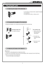
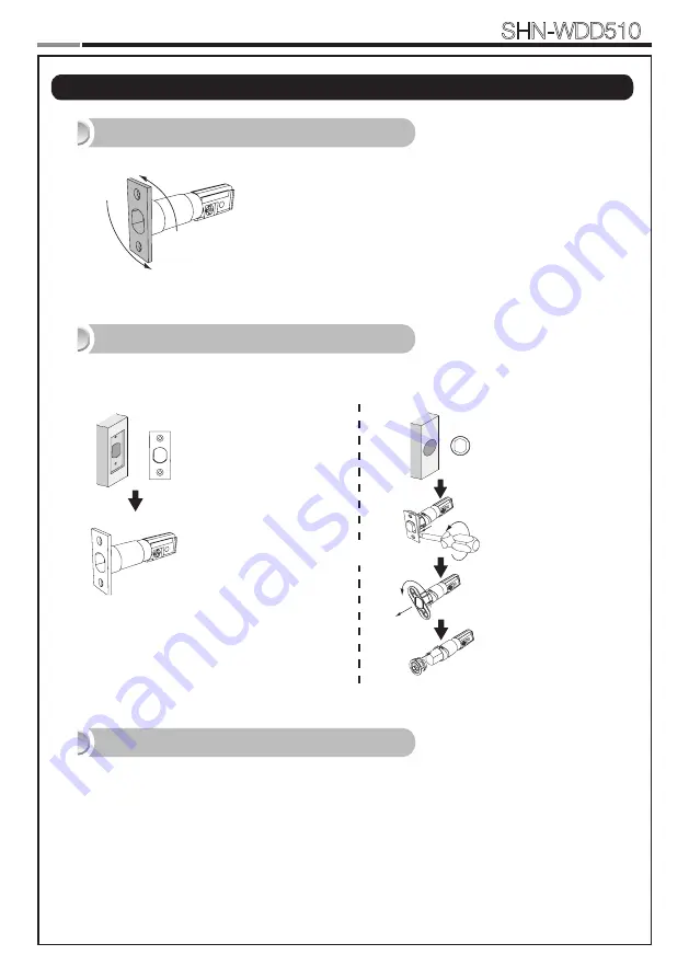
1. Adjusting the length of the dead bolt

180°

Turn the body of the dead bolt to adjust the length 
of the dead bolt.
It can be 60mm (2-3/8”) or 70mm (2-3/4”)

OR

Rectangle Strike hole

: No need to change.

2. Changing the faceplate of the dead bolt

Change the faceplate of the dead bolt following the size of a strike hole.

Round Strike hole

1.  Remove the strike 

faceplate with a 
screw driver.

2.  Turn the inner 

faceplate to take 
out it.

3.  Insert the round 

faceplate.

OR

OR

3. Adjusting the length of the tailpiece

How to cut

1.  Press the V-cut line with pincers to make more cut line.
2.  Hold the end of the tailpiece with pincers.(Cut the tailpiece 5mm longer than the door thickness.)
3.  Bend it up and down until it is separated. 

- For more information, refer to page 31.

Summary of Contents for SHN-WDD510

Page 1: ...Please review all included documentation and use the product as intended Safety precautions must be followed to avoid personal injury or property damage Samsung Smart Door Lock User Guide SHN WDD510 ...

Page 2: ...ecurity of your codes Minimize the lock s exposure to moisture including wet hands and direct contact with liquids Do not exert excessive force or use sharp instrument on the touchscreen Insert the batteries according to correct polarity When the low battery warning sounds replace all batteries immediately Do not mix old batteries with new batteries Use soft dry cloth to clean the lock and avoid c...

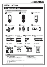
Page 3: ... Interior Mounting Plate C Adjustable Deadbolt D Strike Parts E Magnetic Sensor F Screw for Strike and Dead bolt G1 Screw for mounting plate G2 Screw for Interior unit G3 Batteries J Mechanical Keys I User Manual K Please review all included documentation and use the product as intended Safety precautions must be followed to avoid personal injury or property damage Samsung Smart Door Lo ck User Gu...

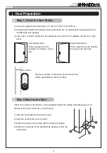
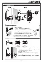
Page 4: ...ection of the deadbolt attach the drilling template page 27 on the side of the door and mark on it with a pen 1 Align the horizontal line across the door 2 Align the vertical line over the door 3 Mark the centers of the holes with the drilling template 4 Mark the centerline of the deadbolt by aligning it with the vertical line Right handed Door When viewed from the Outside the hinge is on the righ...

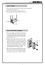
Page 5: ...se hole 2 Measure half the thickness of the door Now measure that distance from where the door stops at the frame when the door is closed toward the door jamb and mark a straight vertical line the length of the door strike plate Draw a horizontal line from the mark you made in Step 1 toward the vertical line Where both lines cross make a 1 25 mm diameter hole 1 2 13 mm in depth 3 Align the holes o...

Page 6: ...aceplate of the dead bolt following the size of a strike hole Round Strike hole 1 Remove the strike faceplate with a screw driver 2 Turn the inner faceplate to take out it 3 Insert the round faceplate OR OR 3 Adjusting the length of the tailpiece How to cut 1 Press the V cut line with pincers to make more cut line 2 Hold the end of the tailpiece with pincers Cut the tailpiece 5mm longer than the d...

Page 7: ...strike hole change the faceplate and insert the deadbolt following right side drawing 2 Installing the Exterior Unit 1 Ensure the Exterior Unit is aligned with the center hole of the deadbolt and Cut the tailpiece 5mm longer than the door thickness refer to the page 31 2 Attach the exterior unit CAUTION The dead bolt must be in a retracted position In case of right handed door insert the tailpiece...

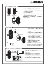
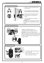
Page 8: ... 3 Installing the Mounting Plate 1 Detach the Interior Mounting Plate from the interior unit 2 Fasten the interior mounting plate with three TH M5x40 G2 90 of the way 3 Align the Exterior Unit with the Interior Mounting Plate and then tighten the screws 4 Cover the rubber pad on the Interior Mounting plate CAUTION Do not over tighten and check the movement of dead bolt by the mechani cal key C C G...

Page 9: ...ensor You can hear the beep sound when the magnetic sensor detects After that press OPEN CLOSE button to check whether the dead bolt works properly 3 Stick the magnetic sensor with attention on the distance CAUTION The gap between the door side and the door frame magnetic sensors should be close enough to be detected OPTION Connection for Video Intercom Connect the cable of video intercom to the I...

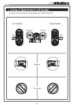
Page 10: ... SHN WDD510 Setting of Right Handed Left Handed All status should be checked while the dead bolt is in OPEN POSITION Right handed Left handed SET REG SET REG SET REG SET REG Tailpiece Thumb turn Left handed Right handed ...

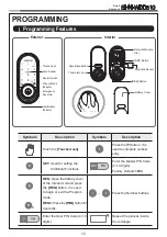
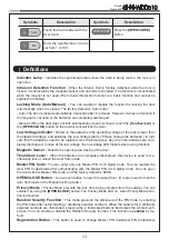
Page 11: ...n Symbols Description Touch the Touchscreen Press the button It is used to complete number entry SET Used for setting the Additional Functions Mstr PIN Enter the Master PIN Code 4 10 digits Factory Default 1234 REG Open the battery cover of the Interior Unit and press the REG button It is used to begin or exit the Program mode REG3 Press the REG button for 3 seconds Press the Number buttons Enter ...

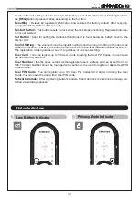
Page 12: ...batteries to indi cate that the batteries need to be replaced Use the Emergency Key when the batteries are com pletely discharged In case of the low voltage the low votage LED flickers when using doorlock Magnetic Sensor Detects the opening and closing of the door Thumbturn Lever When the batteries are completely discharged this device is used to me chanically lock or unlock the door from inside M...

Page 13: ...tting The volume during the input of numbers and opening or locking of the door can be set from Level 0 Level 2 The sound is muted at Level 0 and is at maximum volume at Level 2 The registration mode operates at Level 1 regardless of the sound setting User Card You can register up to 100 User Cards including the User PIN Codes You can open the door with a User Card User Number It is the same numbe...

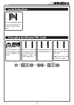
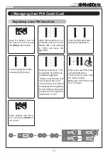
Page 14: ...e touchscreen is illuminated enter the current Master PIN Code default is 1234 and press the button Press the button after pressing the 1 button Enter the new Master PIN Code and press the button Note Master PIN Code must be 4 10 digits REG SET R No 1 100 No 1 100 No 1 100 No 1 100 R 2 2 2 3 3 3 No 1 100 No 1 100 No 1 100 No 1 100 R 2 2 2 3 3 3 Lock Activation Changing the Master PIN Code ...

Page 15: ...and press the button Choose a User Number that has not already been used If don t enter a User Number andpress 0 whenregistering theUserNumberissequential lyassignedontheemprtyUser Number from 1 to 100 Enter a new User PIN Code and press button Touch the Card reader with the Card to register Note User PIN Code must be 4 10 digits Enter another User Num ber or press the REG but ton to quit REG SET ...

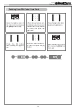
Page 16: ...creen is il luminated enter the current Master PIN Code default is 1234 and press the button Press the button after pressing the 2 button REG SET Press the button after pressing the 3 but ton No 1 100 No 1 100 No 1 100 No 1 100 R 2 2 2 3 3 3 No 1 100 No 1 100 No 1 100 No 1 100 R 2 2 2 3 3 3 No 1 100 No 1 100 No 1 100 No 1 100 R 2 2 2 3 3 3 Enter another User Num ber or press the REG but ton to qui...

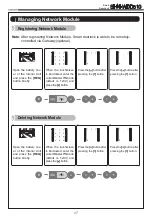
Page 17: ...Registering Network Module Deleting Network Module Press the button after pressing the 1 button R No 1 100 No 1 100 No 1 100 No 1 100 R 2 2 2 3 3 3 No 1 100 No 1 100 No 1 100 No 1 100 R 2 2 2 3 3 3 R 2 2 2 3 3 3 Open the battery cov er of the Interior Unit and press the REG button briefly When the touchscreen is illuminated enter the currentMasterPINCode default is 1234 and press the button Press ...

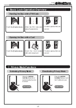
Page 18: ...ter the PIN Code and press the button Press the OPEN CLOSE button for 3 seconds while the door is locked Press the OPEN CLOSE button or turn the Thumbturn lever Activating Privacy Mode Deactivating Privacy Mode Privacy Mode Functions OPEN CLOSE OPEN CLOSE 3 Touch the Touchscreen The door opens within one second Touch the Touchscreen The door opens within one second ...

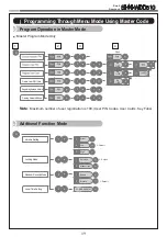
Page 19: ...peration in Master Mode 3 2 4 Master Program Mode Only Delete User PIN Card No 1 100 No 1 100 No 1 100 RegisteringNetworkModule Deleting Network Module R 2 2 2 3 3 3 3 1 Silent 1 Low Default Default Default 2 High 3 Auto lock 1 Manual lock 3 Enable 1 Disable 3 Volume Setting Locking Mode Random Security Mode Local Time Setting S 2 3 4 YYMMDDHHMM Addtional Function Mode ...

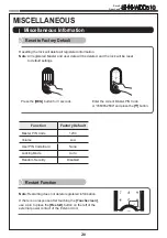
Page 20: ...of the external power contact of the Exterior Unit REG SET Press the REG button for 3 seconds Enter the current Master PIN Code or 4560852580 and press the button Resetting the lock will delete all registered information Note All registered Master and user data will be deleted and the lock will be reset to default settings Function Factory Default Master PIN Code 1234 Volume Low User PIN Code Card...

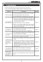
Page 21: ...y been used Delete the de sired User Number and re register Ensure that the User PIN Code is 4 10 digits long Page 15 I can t register the User Card The User Number has already been used Delete the de sired User Number and re register Ensure that the card is touched to the card reader within 20 seconds of entering the User Number Page 15 I entered the PIN Code and pressed the button but the door w...

Page 22: ...k automatically when Auto Locking is set then the lock has been installed incorrectly The Auto Locking function is not activated when the bat teries are completely discharged Check if the batteries are discharged Page 19 There is no response when I touch the Touch screen Use a pin to press the hole on the front of the Exterior unit If doing the above does nothing contact the service center Page 20...

Page 23: ...23 Smart Door Lock SHN WDD510 User No PIN CODE CARD User Name User No PIN CODE CARD User Name User Registration Table ...

Page 24: ...lled and used in accordance with the instructions may cause harmful interference to radio communications However there is no guarantee that interference will not occur in a particular installation If this equipment does cause harmful interference to radio or television reception which can be determined by turning the equipment off and on the user is encouraged to try to correct the interference by...

Page 25: ...ged sub jected to accident nuisance flood fire or acts of God or on which any serial numbers have been altered defaced or removed SAMSUNG SDS and its distributor will not be responsible for any dismantling reassembly or reinstallation charges This warranty contains the entire warranty It is the sole warranty and any prior agreements or representations whether oral or written are either merged here...

Page 26: ...atment of limitations of liability for ordinary or gross negligence so the above limitations or exclusions may not apply to you This Warranty gives you specific legal rights and you may also have other rights which vary from state to state In case of the product defect contact our authorized Customer Service Center In order to exer cise the warranty you must contact our authorized Customer Service...

Page 27: ...27 Smart Door Lock SHN WDD510 Drilling Template Sheet 2 3 8 60mm Backset 5 32 Deep Bore 1 DIA Latch Hole 2 3 8 Ø2 1 8 ...

Page 28: ...28 Smart Door Lock SHN WDD510 ...

Page 29: ...29 Smart Door Lock SHN WDD510 Drilling Template Sheet 2 3 4 70mm Backset 2 3 4 Ø2 1 8 5 32 Deep Bore 1 DIA Latch Hole ...

Page 30: ...30 Smart Door Lock SHN WDD510 ...

Page 31: ...ake more cut line 2 Hold the the end of the tailpiece with pincers 3 Bend it up and down until it is separated How to cut cutting point 1 Check the thickness of your door 2 According to your door thickness cut the tailpiece Note Cut the tailpiece 5mm longer than the door thickness Thickness of the door 5mm ...

Page 32: ...alog its design construction and or its materials Copyright 2014 SAMSUNG SDS Co Ltd All right reserved Reproduction in whole or in part without the express written permission of SAMSUNG SDS is prohibited GC68 02099A ED 02 Product information and customer service contact Smart Door Lock SHN WDD510 ...
Reviews: