30_ camera operation
camera operation
M
`
If the defog mode is set to Auto, and if the amount of fog is reduced, the function level will be
also reduced. If you want to maintain the same level of defogging, set it to Manual.
`
If there is little fog and the manual fog level is high, the screen contrast can get high.
y
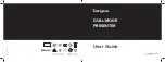
PriVaCY :
Mask an area you want to
hide on the screen.
❶
If the SPECIAL menu screen is
displayed, use the Function Setup
switch so that the arrow indicates
‘PRIVACY’.
❷
Select a desired mode using the
Function Setup switch.
-
AREA : You can select up to 24
PRIVACY areas.
-
MODE : Determines whether to use the area selected in the AREA.
-
MASK COLOR : Determine area color. You can select Green, Red, Blue, Black, White,
Gray.
-
TRANSPARENCY : Adds or removes transparency from the masking area.
-
SEL POS/ XPOS/ YPOS : Adjust the size and position of the selected area.
-
RETURN : Return to the SPECIAL menu.
y
Dis (Digital image stabilizer) :
This function mitigates any picture movement due to
external factors such as wind.
y
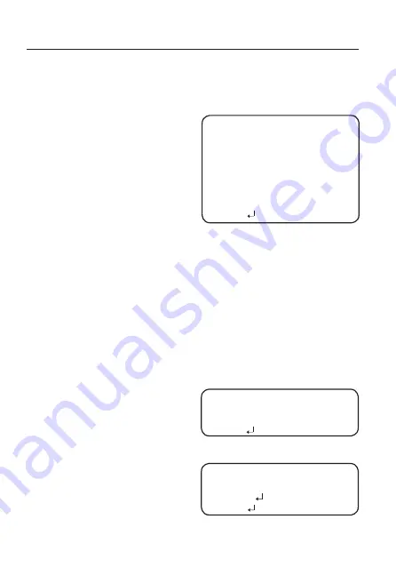
ViDEo analYTiCs(sCb-5000Ph)
❶
If the SPECIAL menu screen is
displayed, use the Function Setup
switch so that the arrow indicates
‘VIDEO ANALYTICS’.
❷
Select a desired mode using the
Function Setup switch.
-
TAMPERING : If the screen view
is obstructed or the
camera location
is changed,
tampering
detection, you can
issue an event signal by setting it.
TAMPERING
▶
1.
SENSITIVITY
MIDDLE
2.
ALARM OUT
3.
RETURN
VIDEO ANALYTICS
▶
1. TAMPERING
OFF
2. MOTION
OFF
3.
RETURN
PRIVACY AREA SETUP
▶
1.
AREA
AREA
1
2.
MODE
OFF
3.
MASK COLOR
GREEN
4.
TRANSPARENCY
OFF
5.
SEL POS
L_TOP
6.
X POS
--------
18
7.
Y POS
-
-------
33
8.
RETURN