


62
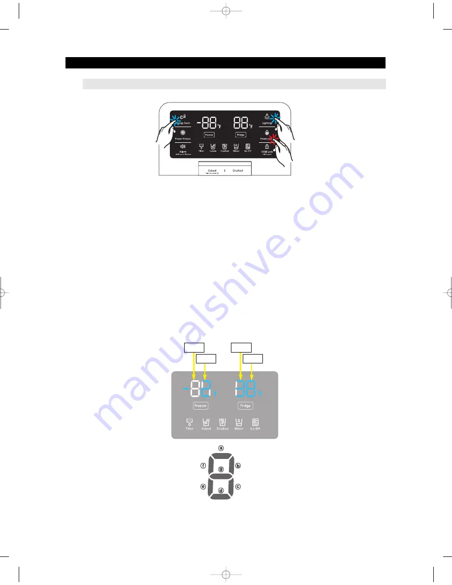
4-1-4. Display function of Load condition
1) If Power Energy Saver Key + Lighting key are pressed simultaneously for 6 seconds during normal
operation, the temperature setting display of fresh food and freezer compartments will blink ALL ON/OFF
with 0.5 for 2 seconds.
2) At this moment, If Power Cool Key after Energy Saver Key + Lighting Key is pressed, load condition
display mode will be returned with alarm.
3) Load condition display mode shows the load that micom signal is outputting.
However, It means that micom signal is outputting, it does not mean whether load is operating or not.
That is to say that though load operation is displayed, load could not be operated by actual load error or
PCB relay error etc. (This function would be applied at A/S.)
4) Load condition display function will maintain for 30 seconds and then normal condition will be returned
automatically.
5) Load condition display is as below. Only the load control LED will blink with 0.5interval in "Display LED"
TROUBLESHOOTING
①
①
①
①
②
②
①
If Energy Saver Key + Lighting key are pressed simultaneously for 6 seconds, ALL ON/OFF will blink
with 0.5interval for 2 seconds.
②
If take the finger off from above keys and press Power Cool Key, load condition mode will be started.
F-10
F-1
R-10
R-1
AW3 SM-EN 2011.3.31 2:55 PM 페이지62 in
Summary of Contents for RF4287HARS
Page 17: ...18 PRODUCT SPECIFICATIONS 2 5 Dimensions of Refrigerator Inches AW3SM EN2011 3 312 52PM 18 in...
Page 86: ...87 TROUBLESHOOTING IPM FREEWHEELING DIODE VOLTAGE VALUE AW3SM EN2011 3 312 56PM 87 in...
Page 96: ...97 TROUBLESHOOTING SPM Internal DIODE Voltage AW3SM EN2011 3 312 56PM 97 in...
Page 98: ...99 TROUBLESHOOTING INVERTER PCB Circuit Diagram AW3SM EN2011 3 312 56PM 99 in...
Page 124: ...125 7 1 Model RFG295AA BETTER 7 WIRING DIAGRAM BLU BLU AW3SM EN2011 3 312 57PM 125 in...
Page 125: ...126 7 2 Model RF4287AA BEST 7 WIRING DIAGRAM AW3SM EN2011 3 312 57PM 126 in...
Page 126: ...127 7 3 Model RFG299AA 7 LCD 7 WIRING DIAGRAM BLU BLU AW3SM EN2011 3 312 57PM 127 in...
Page 127: ...128 7 4 Model RFG294AA SEARS 7 WIRING DIAGRAM AW3SM EN2011 3 312 57PM 128 in...
Page 129: ...130 8 SCHEMATIC DIAGRAM 8 1 2 INVERTER BLOCK RF4287 AW3SM EN2011 3 312 58PM 130 in...
Page 130: ...131 8 2 CIRCUIT DIAGRAM SCHEMATIC DIAGRAM 8 2 1 MAIN AW3SM EN2011 3 312 58PM 131 in...
Page 131: ...132 SCHEMATIC DIAGRAM 8 2 2 INVERTER AW3SM EN2011 3 312 58PM 132 in...


