


82
TROUBLESHOOTING
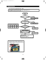
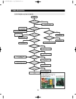
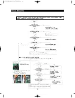
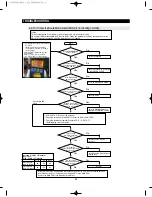
- This refrigerator has BLDC FAN motor. BLDC motor is driven by DC10~12V
- When COMP ON, normally with F-FAN motor.
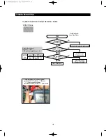
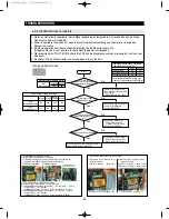
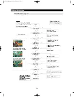
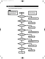
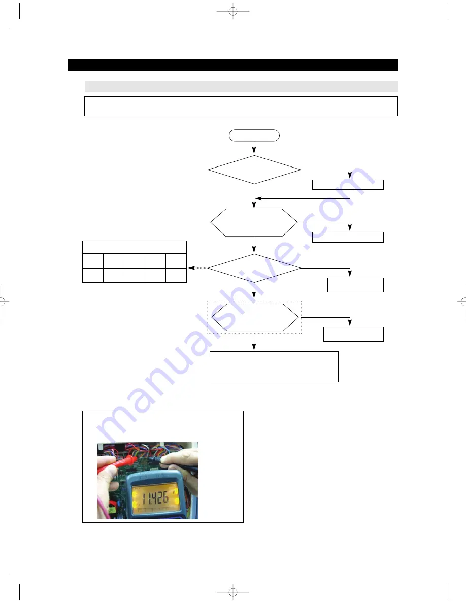
4-2-4. If FAN does not operate(Flex Room - FAN)
Start
Execute manual operation
No
Yes
Yes
No
Yes
Yes
No
No
Is COMPRESSOR ON ?
Is the Flex
Room temperature suitable for
the Fan working?
◆
Predicted Cause
①
FAN-MOTOR troubles itself
②
Bad wiring connections.
③
Wrong Input of the fan motor rotation pulse
Is the voltage between
CN79-"1"(Orange) and "3"(Blue)
(Black) around DC10~12V?
Does DC7~12V alternate
with below DC2V between CN79-
"1"(Orange) and "3"(Blue)
FAN works normally
Operation
temperature/ready
Replace MAIN PCB
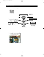
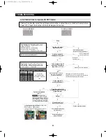
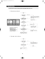
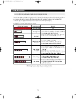
Flex Room control temperature
Sort
Micom
(IC01)
Initial
power On
Heater
off
Working
heater
37
℉
(3
℃
)
42
℉
(6
℃
)
27
℉
(-3
℃
)
32
℉
(0
℃)
Temperaure
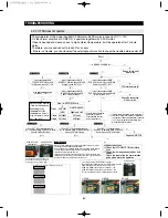
☞
Checking method of Flex Zoon FAN Motor Voltage with the voltage
between CN79-"1"(Orange) and "3"(Blue) shall be less than DC10~12V
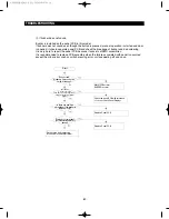
- Additional check if resistance values are different after measurement.
1) Flex Room - FAN
AW3 SM-EN 2011.3.31 2:56 PM 페이지82 in
Summary of Contents for RF4287HARS
Page 17: ...18 PRODUCT SPECIFICATIONS 2 5 Dimensions of Refrigerator Inches AW3SM EN2011 3 312 52PM 18 in...
Page 86: ...87 TROUBLESHOOTING IPM FREEWHEELING DIODE VOLTAGE VALUE AW3SM EN2011 3 312 56PM 87 in...
Page 96: ...97 TROUBLESHOOTING SPM Internal DIODE Voltage AW3SM EN2011 3 312 56PM 97 in...
Page 98: ...99 TROUBLESHOOTING INVERTER PCB Circuit Diagram AW3SM EN2011 3 312 56PM 99 in...
Page 124: ...125 7 1 Model RFG295AA BETTER 7 WIRING DIAGRAM BLU BLU AW3SM EN2011 3 312 57PM 125 in...
Page 125: ...126 7 2 Model RF4287AA BEST 7 WIRING DIAGRAM AW3SM EN2011 3 312 57PM 126 in...
Page 126: ...127 7 3 Model RFG299AA 7 LCD 7 WIRING DIAGRAM BLU BLU AW3SM EN2011 3 312 57PM 127 in...
Page 127: ...128 7 4 Model RFG294AA SEARS 7 WIRING DIAGRAM AW3SM EN2011 3 312 57PM 128 in...
Page 129: ...130 8 SCHEMATIC DIAGRAM 8 1 2 INVERTER BLOCK RF4287 AW3SM EN2011 3 312 58PM 130 in...
Page 130: ...131 8 2 CIRCUIT DIAGRAM SCHEMATIC DIAGRAM 8 2 1 MAIN AW3SM EN2011 3 312 58PM 131 in...
Page 131: ...132 SCHEMATIC DIAGRAM 8 2 2 INVERTER AW3SM EN2011 3 312 58PM 132 in...