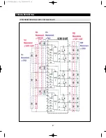
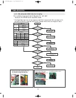
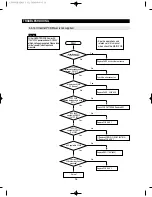
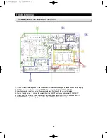
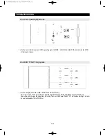

4-3-2. Power Source (HYBRID IC)
1) The power supplied by Noise-Filter is rectified through COMP OLP and the voltage of 300V/DC, rectified
through DIODE, is applied in parallel to the SPM and SMPS area, a compressor operating driver.
2) The power source is the circuit which reduces 300V/DC to each 12V/DC and 15V/DC by Hybrid IC, and
supplied to operate the MICOM for controlling COMP, and SPM.
100
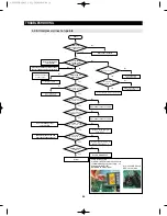
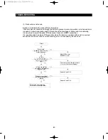
TROUBLESHOOTING
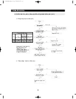
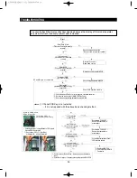
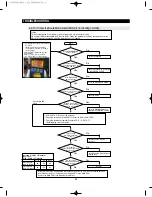
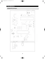
4-3-1. INRUSH CURRENT Protecting Circuit
1) The Power Thermistor prevents an instant inrush of current generated in condenser(C1) when plug in, and
Relay(K1) operates 0.1 second after plug in and the power is supplied by relay afterward.
2) The Fuse 1 is designed as 5A to prevent over current applied to Compressor, and Fuse 2 is designed as 1A to
protect SMPS area and power in secondary part.
AW3 SM-EN 2011.3.31 2:56 PM 페이지100 in
Summary of Contents for RF4287HARS
Page 17: ...18 PRODUCT SPECIFICATIONS 2 5 Dimensions of Refrigerator Inches AW3SM EN2011 3 312 52PM 18 in...
Page 86: ...87 TROUBLESHOOTING IPM FREEWHEELING DIODE VOLTAGE VALUE AW3SM EN2011 3 312 56PM 87 in...
Page 96: ...97 TROUBLESHOOTING SPM Internal DIODE Voltage AW3SM EN2011 3 312 56PM 97 in...
Page 98: ...99 TROUBLESHOOTING INVERTER PCB Circuit Diagram AW3SM EN2011 3 312 56PM 99 in...
Page 124: ...125 7 1 Model RFG295AA BETTER 7 WIRING DIAGRAM BLU BLU AW3SM EN2011 3 312 57PM 125 in...
Page 125: ...126 7 2 Model RF4287AA BEST 7 WIRING DIAGRAM AW3SM EN2011 3 312 57PM 126 in...
Page 126: ...127 7 3 Model RFG299AA 7 LCD 7 WIRING DIAGRAM BLU BLU AW3SM EN2011 3 312 57PM 127 in...
Page 127: ...128 7 4 Model RFG294AA SEARS 7 WIRING DIAGRAM AW3SM EN2011 3 312 57PM 128 in...
Page 129: ...130 8 SCHEMATIC DIAGRAM 8 1 2 INVERTER BLOCK RF4287 AW3SM EN2011 3 312 58PM 130 in...
Page 130: ...131 8 2 CIRCUIT DIAGRAM SCHEMATIC DIAGRAM 8 2 1 MAIN AW3SM EN2011 3 312 58PM 131 in...
Page 131: ...132 SCHEMATIC DIAGRAM 8 2 2 INVERTER AW3SM EN2011 3 312 58PM 132 in...


