51
9.5 Screen Config
To configure a LED display with system configuration files, click
Screen Config
button
fromthe tool bar or select
Tools
->
Screen Config
from the main menu of the NovaLCT-Mars
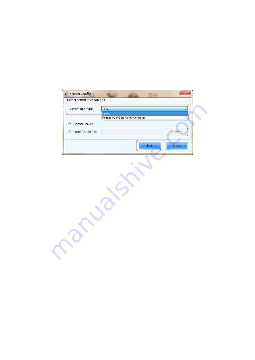
application main interface to open the Screen Config window. Shown in Fig.9-5 is the
Screen Config window.
Fig 9-5
Step 1:
Set the
Current Operation Communication Port
This is the port that connects the sending board (controller) to be configured to the control
computer. If only one serial port of the computer is used to connect the LED display control
system, the used serial port will be automatically set as the current serial port. Otherwise, if
multiple serial ports are used to connect control systems to the computer (one serial port for
one control system), the serial port that is used to connect the control system which is to be
configured should be set as the current serial port. If it's the mode with no sending board,
please set the corresponding network port.
Step 2:
Load system configuration file
Select
Load Config File
option, use
Browse
button to select the system configuration file
to be loaded and then click
Next
. The selected configuration file will be automatically loaded
to the LED display system. The LED display system will have been configured when the
load operation is finished.
Summary of Contents for P10
Page 3: ...3 10 1 Cleaning 104 10 2 Calibration 105 10 3 Replacement steps 106 11 Appendix 119 ...
Page 12: ...12 3 2 Product Appearance ...
Page 13: ...13 ...
Page 14: ...14 3 3 Product design Decomposition chart ...
Page 15: ...15 Assembly drawing ...
Page 16: ...16 3 4 Product main components Module Power Supply Receiving Card Monitoring Card ...
Page 17: ...17 Fan Hub board Power data cables 16pcs DC power cables 8PCS and Flat cables 16 pcs ...
Page 35: ...35 Installation of cabinets Fixing of connect plate ...
Page 42: ...42 8 2 Port of Cabinet and serial number paint ...
Page 59: ...59 ...
Page 68: ...68 ...


