background image

P

W

R

B
A
T
T

SIO1

SIO2

SIO3

SIO4

LAN

PSU-B

SLOT1

SLOT2

SLOT3

SLOT4

SLOT5

SLOT6

SLOT7

SLOT8 SLOT9/SCP MCP/LCP

PSU-B/PSU60

PSU-B

SLOT1

SLOT2

SLOT3

SLOT4

SLOT5

SLOT6

SLOT7

PSU-B/PSU60

PSU-B

SLOT1

SLOT2

SLOT3

SLOT4

SLOT5

SLOT6

SLOT7

SLOT8

SLOT9/SCP MCP/LCP

PSU-B/PSU60

C

1

 -

 S

1

C

1

 -

 S

2

C

1

 -

 S

3

C

1

 -

 S

4

C

1

 -

 S

5

C

1

 -

 S

6

C

1

 -

 S

7

C

1

 -

 S

8

C

1

 -

 S

9

M

C

P

2

P

W

R

B
A
T
T

PSU-B

SLOT1

SLOT2

SLOT3

SLOT4

SLOT5

SLOT6

SLOT7

SLOT8 SLOT9/SCP MCP/LCP

PSU-B/PSU60

PSU-B

SLOT1

SLOT2

SLOT3

SLOT4

SLOT5

SLOT6

SLOT7

PSU-B/PSU60

PSU-B

SLOT1

SLOT2

SLOT3

SLOT4

SLOT5

SLOT6

SLOT7

SLOT8

SLOT9/SCP MCP/LCP

PSU-B/PSU60

C

3

 -

 S

1

L

C

P

2

P

W

R

B
A
T
T

PSU-B

SLOT1

SLOT2

SLOT3

SLOT4

SLOT5

SLOT6

SLOT7

SLOT8 SLOT9/SCP MCP/LCP

PSU-B/PSU60

PSU-B

SLOT1

SLOT2

SLOT3

SLOT4

SLOT5

SLOT6

SLOT7

PSU-B/PSU60

PSU-B

SLOT1

SLOT2

SLOT3

SLOT4

SLOT5

SLOT6

SLOT7

SLOT8

SLOT9/SCP MCP/LCP

PSU-B/PSU60

C

2

 -

 S

1

L

C

P

2

P

W

R

B
A
T
T

SIO1

SIO2

SIO3

SIO4

LAN

PSU-B

SLOT1

SLOT2

SLOT3

SLOT4

SLOT5

SLOT6

SLOT7

SLOT8 SLOT9/SCP MCP/LCP

PSU-B/PSU60

PSU-B

SLOT1

SLOT2

SLOT3

SLOT4

SLOT5

SLOT6

SLOT7

PSU-B/PSU60

PSU-B

SLOT1

SLOT2

SLOT3

SLOT4

SLOT5

SLOT6

SLOT7

SLOT8

SLOT9/SCP MCP/LCP

PSU-B/PSU60

C

1

 -

 S

1

S

C

P

M

C

P

2

Single Cabinet

System

Multiple Cabinet

System

C

3

 -

 S

2

C

3

 -

 S

3

C

3

 -

 S

4

C

3

 -

 S

5

C

3

 -

 S

6

C

3

 -

 S

7

C

3

 -

 S

8

C

3

 -

 S

9

C

2

 -

 S

2

C

2

 -

 S

3

C

2

 -

 S

4

C

2

 -

 S

5

C

2

S

6

C

2

 -

 S

7

C

2

 -

 S

8

C

2

 -

 S

9

C

1

 -

 S

2

C

1

 -

 S

3

C

1

 -

 S

4

C

1

 -

 S

5

C

1

 -

 S

6

C

1

 -

 S

7

C

1

 -

 S

8

J1

S

W

1

J1

S

W

1

F

IGURE


11

-


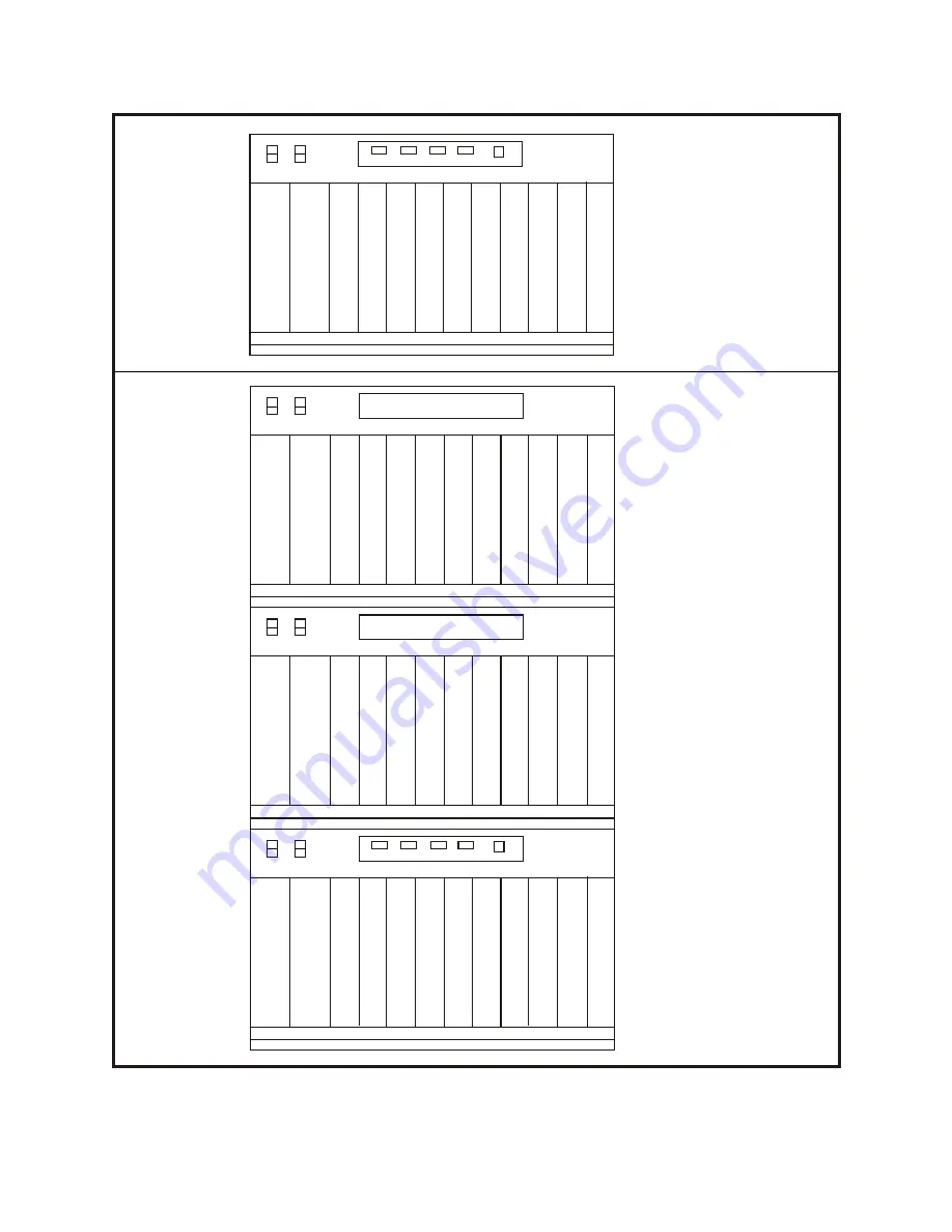
CABINET SLOT NUMBERS


RST

ON

OFF

Summary of Contents for OfficeServ500

Page 1: ...SAMSUNG OfficeServ Installation Guide EnterpriseIPSolutions ...

Page 2: ...imer Samsung Telecoms is not responsible for errors or problems arising from customers not installing programming or operating their Samsung systems as described in this manual Copyright 2003 Samsung Telecoms U K Limited All rights reserved No part of this manual may be reproduced in any form or by any means graphic electronic or mechanical including recording taping photocopy or information retri...

Page 3: ... A14 2000 RTTE TBR4 November 1995 incorporating TBR4 A1 December 1997 EN61000 3 3 1995 EN61000 4 2 1995 98 EN61000 4 3 1996 EN61000 4 4 1995 EN61000 4 5 1995 EN61000 4 6 1996 LVD EN60950 2000 IEC 60950 Third Edition 1999 EN61000 4 11 1994 AS NZS3548 1995 Manufacturer Samsung Electronics Co Ltd 259 Gongdan Dong Gumi City Kyungbuk Korea 730 030 Tae eok Jang General Manager place and date of issue na...

Page 4: ...tem may be provided with the ability to communicate with local computer networks to provide CTI functions and features In this case it is capable of passing information to the computer network via a specified link The system is powered by mains voltage and can optionally be powered by batteries Details of all connections and power arrangements are provided in the instructions for use It should not...

Page 5: ...r system You may need to refer to one or more of them during installation You should have them available for guidance when your system is fully installed and operational y Samsung OfficeServ500 General Description This guide provides an overview of the system including possible structural configurations and hardware features and facilities and specifications y Samsung Combined Systems Programming ...

Page 6: ...nterface Cards 4 1 Control Cards and Daughterboards 4 1 Main Control Processor Card MCP2 4 1 Switch Control Processor Card SCP2 4 3 Local Control Processor Card LCP2 4 4 ESM Daughterboard 4 5 MISC Daughterboard 4 5 SCM Daughterboard 4 5 MFM Daughterboard 4 6 RCM Daughterboard 4 6 MODEM Daughterboard 4 6 IOM Daughterboard 4 7 Interface Cards 4 7 TRUNK B Card 4 7 8TRK Card 4 7 PRI and TEPRI Card 4 7...

Page 7: ...d Door Lock Release 7 3 DECT Base Station DBS 7 3 ISDN Station ISDN Phone G4 FAX etc 7 4 Chapter 8 Connecting Optional Equipment 8 1 Music On Hold Background Music 8 1 External Paging 8 1 Common Bell 8 2 Ring Over Page 8 2 SMDR UCD Traffic Alarms Reports 8 2 PC Programming 8 3 Voice Mail Auto Attendant 8 3 Chapter 9 Installing Keyset Daughterboards 9 1 OfficeServ500 Keyset Daughterboards 9 1 KDB D...

Page 8: ...Figures 1 1 OfficeServ500 Cabinet Dimensions 2 1 System Wall Mounting 2 2 Attaching Legs to Main Cabinet 2 3 Side Cover Mounting Brackets 2 4 Securing Cabinet in Rack 3 1 System Grounding 3 2 Power Input Location 3 3 Setting Voltage on PSU 3 4 Reserve Power Battery Connections 4 1 MCP2 Card 4 2 MCP2 Card Location 4 3 SCP2 Card 4 4 LCP2 Card 4 5 ESM Board 4 6 MCP2 LCP2 Card Screw Locations 4 7 MISC...

Page 9: ...ing an iDCS Series Keyset 7 6a MDF Connections Add On Module to DLI Card 7 6b MDF Connections Add On Module to 16DLI Card 7 7a MDF Connections Single Line Telephone to SLI Card 7 7b MDF Connections Single Line Telephone to 8SLI or 8MWSLI Card 7 7c MDF Connections Single Line Telephone to 16SLI Card 7 7d MDF Connections Single Line Telephone to 16MWSLI Card 7 8a MDF Connections Door Phone and DPIM ...

Page 10: ... being connected that could adversely affect system operation y Ensure that all wires and cables going to and coming from the system are properly routed Do not cross fluorescent lights or run parallel with AC wires y The equipment must be located in an environment that will maintain a temperature range of 32 77 F 0 25 C and a humidity range of 10 90 non condensing y This equipment is to be install...

Page 11: ...502mm 567mm 300mm 1506mm 1004mm FIGURE 1 1 OFFICESERV500 CABINET DIMENSIONS 1 2 Chapter 1 Site Requirements ...

Page 12: ...inet system All system cabinets are identical When unpacking the cabinet s inspect for signs of physical damage If any damage is detected do not attempt installation contact your supplier instead Check to see that each cabinet carton includes the following items y Top cover y Left and right side covers y Front cover y Cabinet leg mounting kit y AC power and DC power cables Check that all additiona...

Page 13: ...or Mounted System Locate the optional legs or locking castors Remove the side and front covers of the cabinet prior to installation to avoid damaging the covers and to allow access to the interior Place the cabinet on a secure surface floor or workbench with the front of the cabinet card slots facing up With the sup plied screws mount the legs or castors on each corner of the cabinet Figure 2 2 Pl...

Page 14: ...Floor Mount One cabinet is to act as the main key service unit KSU the others as expansion cabinets Check that each cabinet carton includes the following items y OfficeServ500 cabinet y Top cover y Left and right side covers y Front cover y Cabinet leg mounting kit y AC power and DC power cables Check that all additional hardware and software is available for installation y Floor mounting equipmen...

Page 15: ...ts to allow cable access 4 Install the cabinets in the rack and secure each cabinet with eight screws in the mounting flange holes Figure 2 4 If mounting in a 600 wide rack leave a space of roughly 5 cm between cabi nets to allow cable access and use the longer HDLC cables 5 Reattach the ground bar to each cabinet 6 Proceed with the installation of the power supply unit s grounding power connectio...

Page 16: ...FIGURES 2 1 TO 2 4 ...

Page 17: ...40 cm 16 2 x 10 2 6mm screws in 1 5 cm 5 8 plywood backboard NOTE Leave screws approximately 4mm 1 8 proud of backboard FIGURE 2 1 SYSTEM WALL MOUNTING ...

Page 18: ...MOUNTING SCREWS FRONT LEFT SIDE BOTTOM FIGURE 2 2 ATTACHING LEGS TO MAIN CABINET ...

Page 19: ...Bracket Bracket Screws Bracket Bracket Screws Ground Bar FIGURE 2 3 SIDE COVER MOUNTING BRACKETS ...

Page 20: ...Mounting Screw Holes Mounting Screw Holes FIGURE 2 4 SECURING CABINET IN RACK ...

Page 21: ...ng bonded building steel cold water pipe or a ground rod using at least 16 AWG 1 3mm copper wire Addition ally the ground between cabinets in a multiple cabinet system must also be at least 16 AWG 1 3mm copper wire The third wire AC ground or FG is connected to the system frame via the ground strap from the ground connector on the AC socket Figure 3 1 A supplementary equipment grounding conductor ...

Page 22: ...unintentionally Consequently a more permanent ground connection is required by connecting a high current voltage capacity ground wire which is bonded to ground at the electric service power entrance or via some other approved method to the system ground bar This is a more secure ground connection which can only be disconnected intentionally These precautions are taken for safety reasons to protect...

Page 23: ...ases the card s rating from 16 to 24 Cards are also allocated priority ratings from 1 to 4 1 being the highest If a higher priority card is added to a system which is already operating to its maximum power supply capacity e g 56 SEPUs lower priority cards will lose an appropriate number of SEPUs in order to allocate them to the new card In this case to ensure that all cards are operating to their ...

Page 24: ...he external 48VDC power source to the system Connect four 12V batteries or eight 6V batteries in series Use the factory supplied wire harness with 91 5cm 36 white and black leads to connect batteries The batteries must be located within one me tre of the KSU The 48VDC cable assembly has a male 3 pin mate and lock connector on the system end Insert this end of the DC cable into the battery BATT con...

Page 25: ...FIGURES 3 1 TO 3 4 ...

Page 26: ...OUND BAR EARTH GROUND MAIN CABINET CONFIGURATION LEFT SIDE VIEW MAIN AND EXPANSION TWO CABINET CONFIGURATION LEFT SIDE VIEW CONNECT GROUND HERE CONNECT EARTH GROUND HERE FG FG FIGURE 3 1 SYSTEM GROUNDING ...

Page 27: ...FIGURE 2 4 Power Input Location FIGURE 3 2 POWER INPUT LOCATION ...

Page 28: ...110 220V selection switch FIGURE 3 3 SETTING VOLTAGE ON PSU ...

Page 29: ...l ON OFF switch incorporating safety trip Battery Cables 48V 4x12 or 8x6 Batteries Battery Connector 3 pin above AC power connectors on side of cabinets Distribution box fixed securely to wall Basic KSU Expn 1 Expn 2 FIGURE 3 4 RESERVE POWER BATTERY CONNECTIONS ...

Page 30: ...erboard must be installed on the card to expand the switch matrix to 1024 channels The card supports the following options y 8 position DIP switch y Memory Backup On Off switch y SmartMedia card slot y 12 LEDs y Three daughterboard positions one with external connections to support a MISC card y Music On Hold internal melody y Two SIO circuits CONFIGURING THE MCP2 CARD Up to three daughterboards c...

Page 31: ...gram Download Enable SW5 Auto Program Download Disable 4 Digit Station Numbers SW6 3 Digit Station Numbers 4 Digit Station Groups SW7 3 Digit Station Groups 4 Digit Trunk Numbers SW8 3 Digit Trunk Numbers Switches 1 4 select the country in which the system is installed Country 1 2 3 4 UK OFF ON OFF OFF Italy ON ON OFF OFF Australia OFF OFF ON OFF Holland OFF ON ON OFF Denmark ON ON ON OFF New Zeal...

Page 32: ...ane connector To prevent accidental damage to the card the MCP LCP connector on the backplane is positioned to mate only with the MCP2 or LCP2 card Other interface cards will not mate with this connector and the MCP2 card will not mate with any other connector LED INDICATIONS The 12 LEDs show the operational status of the MCP2 card SmartMedia card and card slots 1 9 The LED indications are describ...

Page 33: ...ow SWITCH CONTROL PROCESSOR LCP2 DAUGHTERBOARDS Position Type of Daughterboard Allowed LOC1 MFM RCM LOC2 MFM RCM and MISC LOC3 MFM RCM NOTE Only one of any given type of daughterboard may be installed on any one LCP card e g only one MFM can be installed on one card INSTALLING THE LCP2 CARD CAUTION Do not insert the card with system power on Switch the power OFF 1 For each expansion cabinet insert...

Page 34: ...ISC board remove the two screws holding the MCP2 or LCP2 protective casing together Figure 4 6 or remove the four screws holding the SCP2 case together Figure 4 8 and separate the two halves of the case Place the MISC board face down over the two connectors taking care to properly line them up and press gently on the back of the board to seat it The card casing can now be reassembled if all requir...

Page 35: ...gure 4 11 has no selectable options and installs in any available position of the MCP2 card when the system has one cabinet installed Figure 4 1 If the system has more than one cabinet the RCM board must be installed in position LOC3 of the MCP2 card Figure 4 1 any available position of the SCP2 card Figure 4 3 or any available position of the LCP2 card s Figure 4 4 Up to three RCM boards can be i...

Page 36: ...it is fully inserted into the backplane connector PRI and TEPRI Card CAUTION Do not insert the card with system power on Switch the power OFF The TEPRI card Figure 4 16 installs in slot 1 2 or 3 of any cabinet The card supports either E1 or ISDN PRI service The first set of four LEDs on the front of the card provides the status of the service Sync AIS Loss and Layer 2 Active states The second set ...

Page 37: ...E1 T1 E1 Off 2 PRI T1 E1 PRI T1 E1 On 3 NFAS24B NFAS 23B D Off 4 Network User N W User Off 5 AFT Normal Off 6 Not Used Off 7 Not Used Off 8 Card ID On On LED INDICATIONS There are a number of LED indicators on the front of the TEPRI card showing the status of the card The indications are described in Appendix A 8BSI Card CAUTION Do not insert the card with system power on Switch the power OFF The ...

Page 38: ...ensure that it is fully inserted into the backplane connector NOTE Keyset daughterboards will not work if connected to this card SLI Card There are no options to select on this card Figure 4 15 Insert as many SLI cards as are needed into universal slots 1 to 9 Figure 4 2 Push firmly in the middle of both card ejectors on each card to ensure that it is fully inserted into the backplane connector Th...

Page 39: ...rd ejectors on each card to ensure that it is fully inserted into the backplane connector This card automatically detects DTMF or dial pulse signals from an SLT Software and hardware settings are not required The 16SLI has no DTMF receivers it will share the system resources If there is a medium to high concentration of 16SLI cards or traffic one or more MFM daughterboards should be added to a pro...

Page 40: ...MWSLI card follow the same configuration rules when considering a single or double power supply 16MWSLI Card There are no options to select on this card Figure 4 15 Insert up to seven 16MWSLI cards as required into universal slots 1 to 7 Figure 4 2 Push firmly in the middle of both card ejectors on each card to ensure that it is fully inserted into the backplane connector This card automatically d...

Page 41: ... but firmly on the top and bottom of the front edge of the card until the card sits in its connector To configure the card refer to Chapter 12 SVMi 8 16 and Cadence Voice Mail Setup SVMi 16 Card Voice Mail Before installing this card Figure 4 21 it should be correctly configured with a hard disk drive and the appropriate number of voice processing modules Refer to your Voice Mail documentation for...

Page 42: ...p to two MGI3 cards can be installed in a single cabinet Insert each card into any universal card slot Push firmly in the middle of both card ejectors to ensure the card is firmly seated into the backplane connector LED INDICATIONS There are a number of LED indicators on the front of the MGI3 card showing the status of the card The indications are described in Appendix A VDIAL Card The VDIAL card ...

Page 43: ...FIGURES 4 1 TO 4 24 ...

Page 44: ... MFM RCM SCM MFM RCM SCM MFM RCM MISC ESM M C P CHAMP Smart Media MISC1 MISC2 SM S1 S3 S5 S7 S9 MCP LAN S2 S4 S6 S8 ON 1 2 3 4 5 6 7 8 Memory Backup Switch RST ON OFF FIGURE 4 1 MCP2 CARD LAN Connector 2 Insert SmartMedia Card ...

Page 45: ...9 SCP MCP LCP PSU B PSU60 PSU B SLOT1 SLOT2 SLOT3 SLOT4 SLOT5 SLOT6 SLOT7 SLOT8 SLOT9 SCP MCP LCP PSU B PSU60 PSU B SLOT1 SLOT2 SLOT3 SLOT4 SLOT5 SLOT6 SLOT7 SLOT8 SLOT9 SCP MCP LCP PSU B PSU60 M C P CHAMP Smart Media MISC1 MISC2 SM S1 S3 S5 S7 S9 MCP LAN S2 S4 S6 S8 FIGURE 4 2 MCP2 CARD LOCATION ...

Page 46: ...MFM MFM RCM SCM RCM SCM LOC1 LOC2 LOC3 S1 S2 P12 P2 P1 MISC MFM RCM SCM P11 MISC1 MISC2 RX TX S1 SCP S3 S5 S7 S9 S2 S4 S6 S8 S C P SIO FIGURE 4 3 SCP2 CARD 2 ...

Page 47: ...LOC2 LOC1 LOC3 P12 P10 MFM RCM MISC MFM RCM MFM RCM SW1 SW2 P9 P11 P1 MISC1 MISC2 RX TX S1 LCP S3 S5 S7 S9 S2 S4 S6 S8 L C P P4 P3 P5 P6 P4 P4 P4 P8 P7 FIGURE 4 4 LCP2 CARD 2 ...

Page 48: ...P1 P3 U7 U4 U6 U11 U3 P2 U2 U8 U5 U9 U10 U11 FIGURE 4 5 ESM BOARD ...

Page 49: ...Screw Locations FIGURE 4 6 MCP2 LCP2 CARD SCREW LOCATIONS ...

Page 50: ...P1 P2 P3 P4 U1 U2 U4 U4 U13 D3 D4 D2 D1 K2 K1 K3 T3 T4 T2 T1 FIGURE 4 7 MISC BOARD ...

Page 51: ...Screw Locations FIGURE 4 8 SCP2 CARD SCREW LOCATIONS ...

Page 52: ...P1 U7 U4 U5 P2 U2 U1 U6 U3 U8 FIGURE 4 9 SCM BOARD ...

Page 53: ...P1 U7 U4 U5 P2 U2 U1 U6 U3 FIGURE 4 10 MFM BOARD ...

Page 54: ...P2 U3 U4 P1 U1 U8 U5 U9 U2 FIGURE 4 11 RCM BOARD ...

Page 55: ...U10 U9 U8 U5 U7 L1 L2 P1 P2 FIGURE 4 12 MODEM BOARD ...

Page 56: ...P1 MODEM P8 P7 P6 P5 P4 Mounting Screws Mounting Screws LAN SIO4 SIO3 SIO2 SIO1 Line up holes when installing modem FIGURE 4 13 IOM BOARD ...

Page 57: ...LOT5 SLOT6 SLOT7 SLOT8 SLOT9 SCP MCP LCP PSU B PSU 60 PSU B SLOT1 SLOT2 SLOT3 SLOT4 SLOT5 SLOT6 SLOT7 SLOT8 SLOT9 SCP MCP LCP PSU B PSU60 PSU B SLOT1 SLOT2 SLOT3 SLOT4 SLOT5 SLOT6 SLOT7 SLOT8 SLOT9 SCP MCP LCP PSU B PSU 60 IOM BOARD I O FIGURE 4 14 IOM BOARD SLOT IN KSU ...

Page 58: ...X X X X X X xxxxxxxxx TRUNK B CARD 8TRK CARD PRI CARD 8BSI CARD AC15 CARD DLI CARD 16DLI CARD SLI CARD 8SLI CARD 16SLI CARD BRI S0T0 CARD 8MWSLI CARD 16MWSLI CARD FIGURE 4 15 INTERFACE CARDS ...

Page 59: ...MFM P12 P14 P15 P11 SW2 SW1 JP1 JP2 P13 P1 LOS L2 CLK TP2 SYN AIS IPC TPI SIO T E P R I RST E1 T1 1 2 3 4 5 6 7 8 ON FIGURE 4 16 TEPRI CARD ...

Page 60: ...EJECTOR TABS SCREWS FIGURE 4 17 TEPRI CARD SCREW LOCATIONS ...

Page 61: ...ata 41 6 42 3 5 Sync line 17 4 19 5 D channel data 44 6 45 3 6 Sync line 20 4 22 5 D channel data 47 6 48 3 7 Sync line 23 25 PAIR CABLE WITH FEMALE CONNECTOR TO 8BSI CARD RJ 45 CONNECTOR FIGURE 4 18 MDF CONNECTIONS RJ 45 TO 8BSI CARD Champ Pin No Colour B W W B W O O W Bn W W Bn W S S W O R R O R Gn Gn R S R R S Bk B B Bk Gn Bk Bk Gn Bk Bn Bn Bk B Y Y B Y O O Y Bn Y Y Bn Y S S Y O Pu Pu O Pu Gn G...

Page 62: ... U1 U2 Y1 U28 U10 U38 U40 U43 U41 U6 U26 U32 U33 U36 U20 U14 U8 U27 U21 U15 U9 U30 U11 U18 U12 U19 U25 U31 U37 U13 U24 U3 U4 U7 U22 U5 U16 U44 U45 U46 U47 U23 U17 A A xxxxxxxxx CAUTION DO NOT INSERT WITH POWER ON FIGURE 4 19 AA CARD ...

Page 63: ...ICE PROCESSING MODULE PORTS 5 8 VOICE PROCESSING MODULE PORTS 1 4 POWER REGULATOR BACKPLANE CONNECTOR HDD ACCESS RUN INDICATOR SERIAL PORT RESET BUTTON V M 8 A xxxxxxxxx PARALLEL PORT FIGURE 4 20 SVMi 8 CADENCE CARD ...

Page 64: ...FIGURE 4 21 SVMi 16 CARD SERIAL PORT RESET BUTTON VOICE PROCESSING MODULE DISK DRIVE ...

Page 65: ...1 5 ITM3D SW3 SW2 SW4 SW1 PWR RX TX RUN RST SIO 4 1 7 2 3 6 LAN J3 P4 P1 S1 PWR RX SRV IPC RUN TX DSP MOD M G I X Y Z FIGURE 4 22 MGI2 CARD 1 LEDs 2 LAN port 3 RS 232C 4 Reset button 5 J3 connector 5 J3 connector ...

Page 66: ...J1 SW1 P4 P3 P1 P7 MGI3D ITM3D S1 M G I 3 RUN IPC DSP MOD PWR SRV TX RX LAN SIO RST P2 J5 J6 FIGURE 4 23 MGI3 CARD ...

Page 67: ...RAM ROM ROM ROM ROM RAM Clear J2 1F DSP JP1 A law u law FIGURE 4 24 VDIAL CARD ...

Page 68: ...nets see Figure 3 2 in Chapter 3 Plug the other end of each cable into the dedicated AC outlet or power strip Confirm that all expansion cabinets are connected to the main cabinet with ap propriate cables 4 Turn the AC power switch PWR to the ON position on each of the expansion cabinets 5 Turn the AC power switch PWR to the ON position on the main cabinet Processor Card LED Indications After veri...

Page 69: ...f this does not cure the problem unplug and replace the LCP card If the LED still does not light unplug the system re move the expansion cabinet power supply and check the AC fuse located on the bottom Figure 5 1 If the fuse is good but the LED does not light you must correct the problem before continuing Turn off the power switch Unplug all cards using the card ejectors Turn the system on Check t...

Page 70: ...e system Station numbers are assigned in the same manner The lowest slot number containing any type of station card is assigned station numbers beginning with 201 The next highest slot with a sta tion card is assigned numbers following those of the first station card This numbering sequence continues until all of the stations are assigned Default data assigns the keyset in the lowest port to the o...

Page 71: ...110 FUSES VOLTAGE SETTING FIGURE 5 1 FUSES ON PSU ...

Page 72: ...igures 6 1 and 6 2 AC15 Tie Lines Using two pair twisted 24 AWG 0 5mm or 26 AWG 0 4mm jumper wire cross connect each tie line to the AC15 card port of your choice Figure 6 3 Off Premise Extensions OPX Using one pair twisted 24 AWG 0 5mm or 26 AWG 0 4mm jumper wire cross connect sin gle line telephone SLT extensions to telephone company OPX circuits Figure 6 4 Circuits on the SLI card are specifica...

Page 73: ...BRI card can be used as ISDN TE Terminal Equipment or NT2 Network Termination 2 Multi way ISDN Interface When programmed to T mode the default setting this port provides T point Figure 6 6a NOTE When you are connecting a T port to an NT please take care if there is a termination present in any place on the bus other than this BRI card typical 100 Ohm line termination resistance exists on each port...

Page 74: ...FIGURES 6 1 TO 6 6 ...

Page 75: ...FIGURE 6 1 MDF CONNECTIONS LOOP START LINE TO TRUNK B CARD ...

Page 76: ...FIGURE 6 2 MDF CONNECTIONS LOOP START LINE TO 8TRK CARD 25 PAIR CABLE WITH FEMALE CONNECTOR TO ANY 8TRK CARD CONNECT TO ANY CIRCUIT ON ANY 8TRK CARD ...

Page 77: ...FIGURE 6 3 MDF CONNECTIONS AC15 CARD ...

Page 78: ...FIGURE 6 4 MDF CONNECTIONS OFF PREMISES EXTENSION FROM SLI CARD ...

Page 79: ...E PAIR TRANSMIT PAIR CUSTOMER PROVIDED MALE RJ 45 CABLE LOS L2 CLK TP2 SYN AIS IPC TPI SIO T E P R I RST E1 T1 LOS L2 CLK TP2 SYN AIS IPC TPI NETWORK TERMINATING UNIT FIGURE 6 5 MDF CONNECTIONS ISDN PRI CIRCUIT TO TEPRI CARD ...

Page 80: ... 2 9 10 W GY GY W 30 5 11 12 31 6 TX TIP TX RING 3 13 14 R O O R 32 7 RCV TIP RCV RING 3 15 16 R GN GN R 33 8 17 18 34 9 TX TIP TX RING 4 19 20 R GY GY R 35 10 RCV TIP RCV RING 4 21 22 BK BL BL BK 36 11 23 24 37 12 TX TIP TX RING 1 1 2 W BL BL W 26 1 RCV TIP RCV RING 1 3 4 W 0 0 W 27 2 1 3 5 7 2 4 6 8 PAIR PAIR 3 6 4 5 FIGURE 6 6a MDF TRUNK CONNECTIONS TO BRI CARD 26 AWG 0 4mm ...

Page 81: ...ING 2 9 10 W GY GY W 30 5 11 12 31 6 TX TIP TX RING 3 13 14 R O O R 32 7 RCV TIP RCV RING 3 15 16 R GN GN R 33 8 17 18 34 9 TX TIP TX RING 4 19 20 R GY GY R 35 10 RCV TIP RCV RING 4 21 22 BK BL BL BK 36 11 23 24 37 12 TX TIP TX RING 1 1 2 W BL BL W 26 1 RCV TIP RCV RING 1 3 4 W 0 0 W 27 2 1 3 5 7 2 4 6 8 PAIR PAIR FIGURE 6 6b MDF STATION CONNECTIONS TO BRI CARD 26 AWG 0 4mm 5 4 6 3 ...

Page 82: ...sing MMC 720 This rule also applies to all keysets Using one pair twisted 24 AWG 0 5mm or 26 AWG 0 4mm jumper wire cross connect each keyset to the DLI port Figures 7 1a and 7 1b or plug into the keyset daughterboard of your choice see Chapter 9 CAUTION To reduce the risk of fire use only 26 AWG 0 4mm or larger telecomm unication line cord IP Phones An IP phone allows calls through the Ethernet LA...

Page 83: ...ttach it to the keyset Mount the keyset on the wall using the mounting holes Figure 7 4 You may find it easier to attach the wedge to the wall first be fore reattaching the keyset Wall Mounting iDCS Keysets Keysets such as the 28D and 18D have a reversible base wedge which can be removed and re attached to allow the keyset to be fitted to a wall To remove the wedge lay the keyset face down press t...

Page 84: ...To reduce the risk of fire use only 26 AWG 0 4mm or larger telecommunication line cord SLTs with message waiting lamps must be connected to the 8MWSLI or 16MWSLI card Door Phone and Door Lock Release Using one pair twisted 24 AWG 0 5mm or 26 AWG 0 4mm jumper wire cross connect each door phone interface module DPIM to the DLI port Figures 7 8a and 7 8b or plug into the keyset daughterboard of your ...

Page 85: ...a connection between the 8BSI card and the DBS ISDN Station ISDN Phone G4 FAX etc Using two pair twisted 24 AWG 0 5mm or 26 AWG 0 4mm wire cross connect each ISDN TE to the BRI card s S mode port see Figure 6 6b in Chapter 6 As NT2 the BRI card sup ports S points for ISDN TEs ISDN phone G4 FAX etc This S mode ISDN Station Interface Mode must be programmed in MMC 423 first since its default state i...

Page 86: ...FIGURES 7 1 TO 7 8 ...

Page 87: ...FIGURE 7 1a MDF CONNECTIONS DIGITAL KEYSET TO DLI CARD ...

Page 88: ...FIGURE 7 1b MDF CONNECTIONS DIGITAL KEYSET TO 16DLI CARD ...

Page 89: ...IP Phone LAN Ethernet OfficeServ500 Digital Phone MCP2 MGI2 3 16DLI FIGURE 7 2 IP PHONE CONNECTION ...

Page 90: ...MOUNTING HOLES SUPPORT Remove and reverse handset hook 3 FIGURE 7 3 WALL MOUNTING AN OFFICESERV500 KEYSET WITH BASE SUPPORT ...

Page 91: ...FIGURE 7 4 WALL MOUNTING A DCS EURO KEYSET ...

Page 92: ...1 2 1 3 FIGURE 7 5 WALL MOUNTING AN iDCS SERIES KEYSET WITH BASE WEDGE ...

Page 93: ...FIGURE 7 6a MDF CONNECTIONS ADD ON MODULE TO DLI CARD ...

Page 94: ...FIGURE 7 6b MDF CONNECTIONS ADD ON MODULE TO 16DLI CARD ...

Page 95: ...FIGURE 7 7a MDF CONNECTIONS SINGLE LINE TELEPHONE TO SLI CARD ...

Page 96: ...FIGURE 7 7b MDF CONNECTIONS SINGLE LINE TELEPHONE TO 8SLI OR 8MWSLI CARD ...

Page 97: ...FIGURE 7 7c MDF CONNECTIONS SINGLE LINE TELEPHONE TO 16SLI CARD ...

Page 98: ...FIGURE 7 7d MDF CONNECTIONS SINGLE LINE TELEPHONE TO 16MWSLI CARD ...

Page 99: ...FIGURE 7 8a MDF CONNECTIONS DOOR PHONE AND DPIM TO DLI CARD ...

Page 100: ...FIGURE 7 8b MDF CONNECTIONS DOOR PHONE AND DPIM TO 16DLI CARD ...

Page 101: ... receive a music source system generated tone or NO MUSIC when it is put on hold Each keyset can receive a music source or NO MUSIC for background music External Paging Each MISC daughterboard provides a voice pair and a dry contact pair to be used with cus tomer provided paging equipment Connect the customer provided paging equipment to the page output pins of a MISC daughterboard Figure 8 2 The ...

Page 102: ...cial AC power to these contacts Ring Over Page When a customer provided paging system is installed incoming calls can be assigned to ring over page ROP Program the line or lines to ring a hunt group Using MMC 601 assign ROP as a destination in this hunt group ROP can be used for day or night operation or both SMDR UCD Traffic Alarm Reports To receive SMDR Station Message Detail Recording UCD stati...

Page 103: ... cable must not exceed 300 feet For information on programming the ports refer to MMC 804 in the Samsung Combined Sys tems Programming Manual Voice Mail Auto Attendant The system provides special programming and hardware for use with a customer provided voice mail auto attendant VM AA system All single line stations on the SLI and 8SLI cards provide a disconnect signal required for VM AA operation...

Page 104: ...FIGURES 8 1 TO 8 6 ...

Page 105: ...CUSTOMER PROVIDED MUSIC SOURCE 1 CUSTOMER PROVIDED MUSIC SOURCE 2 1 2 3 4 5 6 7 8 8 CONDUCTOR PLUG MISC 1 MISC 2 RED GREEN BROWN ORANGE FIGURE 8 1 MDF CONNECTIONS MOH SOURCE TO MISC BOARD ...

Page 106: ...OR LOUD BELL 8 CONDUCTOR PLUG 8 CONDUCTOR PLUG 6 CONDUCTOR PLUG RELAY CONTACT 3 2 7 RELAY CONTACT 2 3 6 RELAY CONTACT 1 4 5 ORANGE BROWN PAIR BLACK YELLOW PAIR RED GREEN PAIR WHITE OR GREY BLUE BLACK YELLOW 1 2 3 4 5 6 7 8 1 2 3 4 5 6 7 8 FIGURE 8 2 MDF CONNECTIONS PAGING LOUD BELL AMP TO MISC BOARD ...

Page 107: ...MISC 2 1 2 3 4 5 6 7 8 8 CONDUCTOR PLUG 6 CONDUCTOR PLUG RELAY CONTACT 3 2 7 RELAY CONTACT 2 3 6 RELAY CONTACT 1 4 5 BROWN ORANGE PAIR BLACK YELLOW PAIR RED GREEN PAIR FIGURE 8 3 MDF CONNECTIONS COMMON BELL TO MISC BOARD ...

Page 108: ...7 SLOT8 SLOT9 SCP MCP LCP PSU B PSU60 PSU B SLOT1 SLOT2 SLOT3 SLOT4 SLOT5 SLOT6 SLOT7 SLOT8 SLOT9 SCP MCP LCP PSU B PSU60 PSU B SLOT1 SLOT2 SLOT3 SLOT4 SLOT5 SLOT6 SLOT7 SLOT8 SLOT9 SCP MCP LCP PSU B PSU60 SIO PORTS IOM BOARD FIGURE 8 4 SIO CONNECTOR LOCATIONS Daughterboards IOM BOARD ...

Page 109: ...N FIGURE 7 6 IOM BOARD PRINTER RXD 2 TXD 3 GND 5 DTR 4 2 3 7 20 2 3 5 4 3 2 7 20 OR 9 PIN 25 PIN FIGURE 7 6 IOM BOARD PRINTER RXD 2 TXD 3 GND 5 DTR 4 2 3 7 20 2 3 5 4 3 2 7 20 OR 9 PIN 25 PIN FIGURE 7 6 IOM BOARD PRINTER RXD 2 TXD 3 GND 5 DTR 4 2 3 7 20 2 3 5 4 3 2 7 20 OR 9 PIN 25 PIN FIGURE 7 6 PIN CONNECTIONS FOR IOM BOARD TO PRINTER IOM BOARD PRINTER RXD 2 TXD 3 GND 5 DTR 4 2 3 7 20 FIGURE 8 5...

Page 110: ...telephone SLT The KDB S will only operate when the keyset is connected to an 8 port DLI card so that it can use the second B channel Each port on this card is intended for connection to one tele phone CAUTION Connecting multiple telephones to a port may result in incorrect operation or damage to the card NOTE The circuitry on a KDB S does not provide a loop open disconnect signal or have the over ...

Page 111: ...cting a single line telephone use a line cord fitted with a master ing unit The second method is to use a multi pair station cable connecting separate station jacks to the first two pairs A line cord can now be connected between the daughterboard and the second jack This returns the daughterboard port to the MDF for cross connection to another cable run DCS Keyset Daughterboards There are two type...

Page 112: ... 3 Remove the two knockouts marked Expansion Module and Extra on the base Figure 9 1 using a flat bladed screwdriver or similar tool 4 Position the daughterboard over the Expansion Module connector and push it into the socket 5 Secure the daughterboard onto the keyset using the screws provided Connecting Devices To DCS Daughterboards There are two methods for connecting devices to keyset daughterb...

Page 113: ... only operate when the keyset is connected to an 8 port DLI card so that it can use the second B channel Each port on this card is intended for connection to one tele phone CAUTION Connecting multiple telephones to a port may result in incorrect operation or damage to the card NOTE The circuitry on a FKDBS does not provide a loop open disconnect signal or have the over voltage protection necessary...

Page 114: ...g the screws provided 6 Replace the base wedge If you removed cables from cable runs replace them as required NOTE Figure 9 2 shows the 28D keyset However the procedure is the same for 18D keysets Connecting Devices To iDCS Daughterboards There are two methods for connecting devices to keyset daughterboards The simplest method is to connect a device e g another keyset directly by means of an RJ11 ...

Page 115: ...FIGURES 9 1 TO 9 2 ...

Page 116: ...KOUTS 1 BEFORE FITTING DAUGHTERBOARD UNPLUG LINE CORD EXTRA TEL HANDSET EXTRA TEL HANDSET DAUGHTERBOARD 2 AFTER FITTING DAUGHTERBOARD A SCREW HOLES FOR SECURING DAUGHTERBOARD DAUGHTERBOARDS FIGURE 9 1 CONNECTING DCS KEYSET ...

Page 117: ...FIGURE 9 2 CONNECTING iDCS 28D AND 18D KEYSET DAUGHTERBOARDS ...

Page 118: ... the SmartMedia card to the cards listed above using MMC 818 Program Download and will be stored in the cards flash memory The cards will automati cally reboot load and run the new software when the download process is complete Using PCMMC over a LAN connection to the system the files can be uploaded to the SmartMe dia card The files are first uploaded to the MCP2 card and then transferred to the ...

Page 119: ...er Database Copy where it is stored as a single file This save can be performed manually or the system can be programmed to save the database automatically at a designated time every day Using PCMMC the database can be downloaded from the system and stored on the PC or it can be uploaded from the PC to the system The database uploaded from PCMMC is not stored in the SmartMe dia card but is loaded ...

Page 120: ... s This is done using MMC 806 Card Pre Install for each new card that is installed 3 The new card s must be assigned directory numbers according to the system numbering plan in MMC 724 Make a note of the software port assignments of the new cards so the ports can be assigned the correct numbers These software port assignments are shown in Figure 11 1 Grading the OfficeServ500 for DTMF Receivers Di...

Page 121: ...TEPRI 8BSI AC15 DLI 16DLI SLI 4 8 0 0 0 3 0 0 0 8SLI 16SLI BRI 8MWSLI 16MWSLI AA SVMi 8 16 Cadence MGI 8 16 0 8 16 0 0 0 To calculate your requirement 1 Add together the MFMU values of all cards in the system to obtain the rate as shown in the following table Total MFMU Value Rate Up to 20 3 20 40 4 More than 40 5 2 Use the following calculation to obtain a number between 0 and 3 Total MFMUs Rate ...

Page 122: ... therefore you require one SCM and one MFM NOTE 1 The 4 circuit SLI card 4SLI has four dedicated analogue DTMF receivers One receiver is dedicated to each port on this card and only this card These analogue receivers cannot be used by any other system device They are NOT a common resource 2 The AA card has eight DSPs that are dedicated exclusively for AA ports They cannot be used for any other pur...

Page 123: ...U60 C3 S1 LCP2 P W R B A T T PSU B SLOT1 SLOT2 SLOT3 SLOT4 SLOT5 SLOT6 SLOT7 SLOT8 SLOT9 SCP MCP LCP PSU B PSU60 PSU B SLOT1 SLOT2 SLOT3 SLOT4 SLOT5 SLOT6 SLOT7 PSU B PSU60 PSU B SLOT1 SLOT2 SLOT3 SLOT4 SLOT5 SLOT6 SLOT7 SLOT8 SLOT9 SCP MCP LCP PSU B PSU60 C2 S1 LCP2 P W R B A T T SIO1 SIO2 SIO3 SIO4 LAN PSU B SLOT1 SLOT2 SLOT3 SLOT4 SLOT5 SLOT6 SLOT7 SLOT8 SLOT9 SCP MCP LCP PSU B PSU60 PSU B SLOT...

Page 124: ...ing no calls are in progress STEADY GREEN Voice Mail software is running one or more calls are in progress FLASHING GREEN Voice Mail software is initializing and is not ready to process calls Reset Button The red button marked RST is the reset button Pressing this button during operation will disconnect all callers to the VM system and restart the card Power Requirements All the power to run this ...

Page 125: ...ng steps It is necessary to perform these now so that the VM system will be initialized accordingly MMC 601 All VM ports must be assigned to group 549 L systems or 529 S and M systems Select either SEQUENTIAL or DISTRIBUTED ring mode Set group type to BI VMS MMC 751 Select NO for each station for which you DO NOT want to create a mailbox 5 INITIALIZE VM In MMC 750 set the DOWNLOAD option to YES an...

Page 126: ...ystem power is switched off 3 Replace the MCP card with the MCP2 card First remove any daughterboards from the MCP card and install them on the MCP2 card NB An IPM or LAN board is not required on an MCP2 card Also install the SmartMedia card containing the OfficeServ500 version of the software 4 Replace the SCP card and LCP card with the SCP2 and LCP2 card respectively 5 Install the additional har...

Page 127: ...tus OFF There is no link from the SCP2 card S3 ON The link from the SCP2 card is being set up Flicker indicates a message has been transmitted LCP2 1 HDLC RX Receive Status OFF There is no link from the LCP card S4 ON The link from the LCP card is being set up Flicker indicates a message has been received LCP2 1 HDLC TX Transmit Status OFF There is no link from the LCP card S5 ON The link from the...

Page 128: ...idle or no card installed S1 S9 ON One or more circuits busy Flicker indicates the card has a fault SCP2 HDLC TX Transmit Status OFF There is no link from the SCP2 card TX ON The link from the SCP2 card is being set up Flicker indicates a message has been transmitted SCP2 HDLC RX Receive Status OFF There is no link from the SCP2 card RX ON The link from the SCP2 card is being set up Flicker indica...

Page 129: ...1 TP2 show the span type TP1 TP2 E1 mode OFF OFF E1 PRI mode OFF ON T1 mode ON OFF MODE T1 PRI mode ON ON LCP2 HDLC TX Transmit Status OFF There is no link from the LCP2 card TX ON The link from the LCP2 card is being set up Flicker indicates a message has been transmitted LCP2 HDLC RX Receive Status OFF There is no link from the LCP2 card RX ON The link from the LCP2 card is being set up Flicker ...

Page 130: ...r Data is being transmitted OFF Data is not being transmitted SRV Displays if service is possible ON Service is possible OFF Service is not possible Flicker Program is being modified or configura tion is being downloaded DSP Displays if the DSP channel is being used OFF All channels are not in use Flicker 400ms 1 to 7 channels are in use Flicker 200ms 8 to 11 channels are in use Flicker 100ms 12 t...

Page 131: ...RUN Displays the operational status of the card ON Card is operating normally OFF Card is not operating normally IPC Displays if messages are being transferred between the card and the MCP2 Flicker Messages are transferred normally OFF No message transfer DSP Displays the usage rate of the DSP channel Flicker DSP channel is being used Flickers every second for 1 to 4 channels every 0 5 sec ond for...

Page 132: ...Samsung Telecoms U K Limited Brookside Business Park Greengate Middleton Manchester M24 1GS ...

Reviews: