10-2 Viewing the Connection Panel
10 Operating Instructions and Installation
10-2
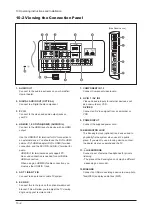
1. AUDIO OUT
Connect to the audio input jacks on your Amplifier/
Home theater.
2. DIGITAL AUDIO OUT (OPTICAL)
Connect to a Digital Audio component.
3. PC IN
Connect to the video and audio output jacks on
your PC.
4. HDMI IN 1,2,3 /DVI IN(HDMI1) (AUDIO R/L)
Connect to the HDMI jack of a device with an HDMI
output.
Use the HDMI/DVI IN terminal for DVI connection to
an external device. You should use the DVI to HDMI
cable or DVI-HDMI adapter (DVI to HDMI) for video
connection, and the DVI IN 'R-AUDIO-L' terminal for
audio.
- HDMI/DVI IN terminal does not support PC.
- No sound connection is needed for an HDMI to
HDMI connection
- When using an HDMI/DVI cable connection, you
must use the HDMI IN 1 jack.
5. ANT 1 IN/ANT 2 IN
Connect to an antenna or cable TV system.
6. EX LINK
Connect this to the jack on the optional wall mount
bracket. This will allow you to adjust the TV viewing
angle using your remote control.
7. COMPONENT IN 1,2
Connect Component video/audio.
8. AV IN 1 / AV IN 2
Video and audio inputs for external devices, such
as a camcorder or VCR.
S-VIDEO
Connect an S-Video signal from a camcorder or
VCR.
9. POWER INPUT
Connect the supplied power cord.
10. KENSINGTON LOCK
The Kensington lock (optional) is a device used to
physically fix the system when used in a public
place. If you want to use a locking device, contact
the dealer where you purchased the TV.
11.
HEADPHONE
Connect a set of external headphones for private
listening.
- The place of the Kensington Lock may be different
depending on its model.
12. WISELINK
Connect an USB mass storage device to view photo
files(JPEG) and play audio files (MP3).
[Side Panel Jacks]
Summary of Contents for LN-T4065F
Page 17: ...7 Block Diagrams 7 2 7 2 Audio Block Diagram ...
Page 18: ...13 Circuit Descriptions 13 1 13 Circuit Descriptions 13 1 Main Board Block Description ...
Page 19: ...13 Circuit Descriptions 13 2 13 2 Video Signal Path ...
Page 20: ...13 Circuit Descriptions 13 3 13 3 Audio Signal Path 13 3 Side AV Signal Path ...
Page 21: ...13 Circuit Descriptions 13 4 Menu ...
Page 112: ...5 Exploded View Parts List 5 3 M0014 M0013 M0013 T0003 M0215 T0175 5 3 LNT4665F Exploded View ...
Page 118: ...10 Operating Instructions and Installation 10 3 10 3 Remote Control ...
Page 121: ...12 PCB Diagram 12 2 12 2 IP BOARD Diagram 46 ...
Page 125: ...1 Precautions 1 4 Memo ...
Page 131: ...2 Product Specifications 2 6 Memo ...
Page 133: ...14 Reference Infomation 14 2 14 1 2 Supported Mode 1 ...
Page 158: ...4 Troubleshooting 4 3 WAVEFORMS 1 2 PC Input V Sync H Sync 3 LVDS Out CLK ...
Page 166: ...4 Troubleshooting 4 11 WAVEFORMS 6 Tuner CVBS Out Pattern Grey Bar 7 TS DATA Out Clk Data 0 ...
Page 173: ...4 Troubleshooting 4 18 Memo ...
Page 174: ...8 Wiring Diagrams 8 1 8 Wiring Diagram ...
Page 175: ...8 Wiring Diagrams 8 2 Memo ...


