


4 Troubleshooting
4-6
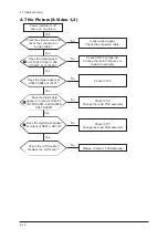
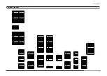
4-4 No Picture (Tuner_CVBS)
Check the RF source and
check the connection of RF
cable ?
Input the RF signal.
Check the connected cable.
Yes
Does the signal appear at
the main splitter cable ?
Check RF111.
Check splitter cable connection.
Change the main PCB assembly
or splitter cable.
Yes
Does the signal appear at
TU112 ?
Check TU501.
Change the main PCB assembly or tuner.
Yes
Yes
Check the LVDS cable ?
Replace the LCD panel ?
Yes
Power Indicator is off.
Lamp on, no picture.
No
No
No
Please, Contact 1 800 Samsung
No
8
Does the digital data
appear at output of R1034-7,
R1039,RA061~063,RA065,R
A067,RA068?
Check IC101
Change the main PCB assembly
Yes
Does the digital data appear
at output of RA071~RA712?
Check IC071
Change the main PCB assembly
No
No
6
7
Summary of Contents for LN-T4065F
Page 17: ...7 Block Diagrams 7 2 7 2 Audio Block Diagram ...
Page 18: ...13 Circuit Descriptions 13 1 13 Circuit Descriptions 13 1 Main Board Block Description ...
Page 19: ...13 Circuit Descriptions 13 2 13 2 Video Signal Path ...
Page 20: ...13 Circuit Descriptions 13 3 13 3 Audio Signal Path 13 3 Side AV Signal Path ...
Page 21: ...13 Circuit Descriptions 13 4 Menu ...
Page 112: ...5 Exploded View Parts List 5 3 M0014 M0013 M0013 T0003 M0215 T0175 5 3 LNT4665F Exploded View ...
Page 118: ...10 Operating Instructions and Installation 10 3 10 3 Remote Control ...
Page 121: ...12 PCB Diagram 12 2 12 2 IP BOARD Diagram 46 ...
Page 125: ...1 Precautions 1 4 Memo ...
Page 131: ...2 Product Specifications 2 6 Memo ...
Page 133: ...14 Reference Infomation 14 2 14 1 2 Supported Mode 1 ...
Page 158: ...4 Troubleshooting 4 3 WAVEFORMS 1 2 PC Input V Sync H Sync 3 LVDS Out CLK ...
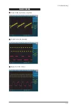
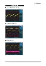
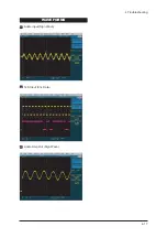
Page 166: ...4 Troubleshooting 4 11 WAVEFORMS 6 Tuner CVBS Out Pattern Grey Bar 7 TS DATA Out Clk Data 0 ...
Page 173: ...4 Troubleshooting 4 18 Memo ...
Page 174: ...8 Wiring Diagrams 8 1 8 Wiring Diagram ...
Page 175: ...8 Wiring Diagrams 8 2 Memo ...