3 Alignments and Adjustments
3-2
3-2 Factory Mode Adjustments
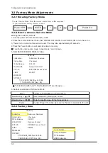
3-2-1 Entering Factory Mode
To enter 'Service Mode' Press the remote -control keys in this sequence :
- If you do not have Factory remote - control
3-2-2 How to Access Service Mode
■
Using the Customer Remote
1.Turn the power off and set to stand-by mode
2.Press the remote buttons in this order; POWER OFF-MUTE-1-8-2-POWER ON to turn the set on.
3.The set turns on and enters service mode. This may take approximately 20 seconds.
4.Press the Power button to exit and store data in memory.
※
※
If you fail to enter service mode, repeat steps 1 and 2 above.
5.Initial SERVICE MODE DISPLAY State
Power OFF
1
8
2
Power On
MUTE
3-2-3 Factory Data
NTSC-RF
T-TULPAUS0_0025 Dec 26 2006
T-TULPAUS5-C007 [Sec : 08]
Calibration
Option Byte
White Balance
W/B MOVIE
SVP-LX
FBE2
MSP44XX
NTP3000
Submicom Download
Checksum
KS1410
Dynamic Contrast
EEPROM Access Count
RESET
6. Buttons operations withn Service Mode
※
"T-TULPUS0-0025" and "T-TULPAUS5-C007" are firmware.......
Menu
Full Menu Display/Move to Parent Menu
Item Selection by Moving the Cursor
Data Increse/Decrese for the Selected Item
Cycles through the active input source that are connected to the unit
Direction Keys
Direction Keys
Source
NTSC-RF
T-TULPAUS0_0025 Dec 26 2006
T-BRDPAUS5_C007 [Sec : 08]
Calibration
Option Byte
White Balance
W/B MOVIE
SVP-PX
FBE2
MSP4440K
NTP3000
Submicom Download
Checksum
KS1410
Dynamic Contrast
EEPROM Access Count
RESET
AV Calibration
Comp Calibration
PC Calibration
HDMI Calibration
Summary of Contents for LN-T4065F
Page 17: ...7 Block Diagrams 7 2 7 2 Audio Block Diagram ...
Page 18: ...13 Circuit Descriptions 13 1 13 Circuit Descriptions 13 1 Main Board Block Description ...
Page 19: ...13 Circuit Descriptions 13 2 13 2 Video Signal Path ...
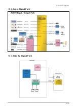
Page 20: ...13 Circuit Descriptions 13 3 13 3 Audio Signal Path 13 3 Side AV Signal Path ...
Page 21: ...13 Circuit Descriptions 13 4 Menu ...
Page 112: ...5 Exploded View Parts List 5 3 M0014 M0013 M0013 T0003 M0215 T0175 5 3 LNT4665F Exploded View ...
Page 118: ...10 Operating Instructions and Installation 10 3 10 3 Remote Control ...
Page 121: ...12 PCB Diagram 12 2 12 2 IP BOARD Diagram 46 ...
Page 125: ...1 Precautions 1 4 Memo ...
Page 131: ...2 Product Specifications 2 6 Memo ...
Page 133: ...14 Reference Infomation 14 2 14 1 2 Supported Mode 1 ...
Page 158: ...4 Troubleshooting 4 3 WAVEFORMS 1 2 PC Input V Sync H Sync 3 LVDS Out CLK ...
Page 166: ...4 Troubleshooting 4 11 WAVEFORMS 6 Tuner CVBS Out Pattern Grey Bar 7 TS DATA Out Clk Data 0 ...
Page 173: ...4 Troubleshooting 4 18 Memo ...
Page 174: ...8 Wiring Diagrams 8 1 8 Wiring Diagram ...
Page 175: ...8 Wiring Diagrams 8 2 Memo ...


