


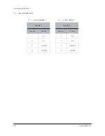


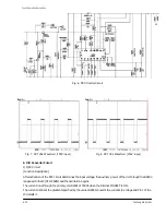


Fig. 5. Oscillation Waveform of the Auxiliary Power Circuit
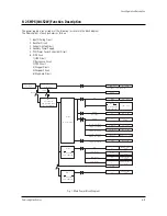
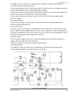
5. PFC Circuit
[Function Description]
When the auxiliary power circuit begins to oscillate, Vcc voltage is applied to the control IC (L4981)
of the PFC circuit to start the oscillation.
The oscillation frequency is determined by the resistor R8267 (connected to Pin 17)
and the condenser C8265 (connected to Pin 18).
Pin 14 detects the resistor’s divided output voltage for control purposes.
This voltage and the AC voltage is resistor divided to be fed to Pin 4, and the IC multiplies it internally in order to
dictate the set point for the main FET.
Hence, the output voltage is controlled by the resistor divided output, and the input current
has the same waveform (sine wave) as the AC power resulting in 100% of the power factor.
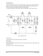
[Protection Features]
-Over-Voltage Protection
The Voltage limiting type Over-Voltage Protection feature limits the voltage under the set point and narrows the
ON width of the FET while the hit occurs, and the Overshoot or the “no control” by the load variation.
The set point value of the protection voltage is controlled by R8231, R8232, R8233, and R8234.
(Set the main power to around 440V)
-Over Current Protection
The detection resistor R8202 converts the currents to voltage and Pins 2 and 8 of the control IC detect it.
The protection eoccurs by narrowing the pulse width to limit the output when the increased current results in
over-voltage at the detection resistor.
-Overheating Protection
The IC has no overheating protection. The posistor (TH8221) is positioned on the cooling fin on the main FET to
stop the circuit when overheating has been caused by overloading or other reasons.
Samsung Electronics 6-
13
Circuit Operation Description
Summary of Contents for D61B
Page 10: ...3 2 Samsung Electronics MEMO ...
Page 30: ...4 20 Samsung Electronics MEMO ...
Page 38: ...Alignment and Adjustments 2 8 Samsung Electronics MEMO ...
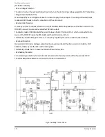
Page 61: ...Fig 18 Chopper Circuit 6 22 Samsung Electronics Circuit Operation Description ...
Page 85: ...8 8 Samsung Electronics MEMO ...
Page 99: ...9 14 Samsung Electronics MEMO ...
Page 106: ...Samsung Electronics Schematic Diagrams 10 7 10 7 SMPS 2 ...
Page 107: ...Schematic Diagrams 10 8 Samsung Electronics 10 8 SMPS 3 ...
Page 108: ...Samsung Electronics Schematic Diagrams 10 9 10 9 SMPS 4 ...