[Protection Features]
- Over-vVoltage Protection
The Latch circuit will be activated to stop the circuit when the Vcc terminal voltage exceeds the OVP activating
voltage Vcc(OVP)=31.2V(TYP).
When stopped by over-voltage, wait about 5 minutes to apply the input again. The voltage of the electrolytic
condenser C8133 needs to drop for cancellation of the Latch circuit.
- OverCurrent Protection
A pulse by pulse over-current protection circuit (STR-A6151) detects the peak value of the drain current of the
MOSFET per every 1 pulse and reverses the PRC latch output.
The detector resistor (R8132) detects the current between the OCP terminal (Pin 1) which is connected to the
source of the MOSFET inside the STR-A6151 and the GND terminal (Pin 3).
This feature prevents damage from the over-current by regulating the current under the allowed load.
- Overload Protection
It provides UVLO (Under Voltage Lockout) during an overload status (the drain current is limited by OCP
behavior) caused by a malfunction of the loading side.
This feature protects the IC in case of overload to the secondary side.
- Overheating Protection
For overheating protection, the latch circuit is activated when the temperature of the chip exceeds 140 ºC
The actual temperature detection is done by the control circuit element.
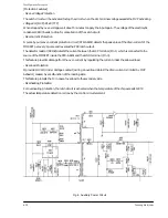
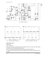
Fig. 4. Auxiliary Power Circuit
6-
12
Samsung Electronics
Circuit Operation Description
Summary of Contents for D61B
Page 10: ...3 2 Samsung Electronics MEMO ...
Page 30: ...4 20 Samsung Electronics MEMO ...
Page 38: ...Alignment and Adjustments 2 8 Samsung Electronics MEMO ...
Page 61: ...Fig 18 Chopper Circuit 6 22 Samsung Electronics Circuit Operation Description ...
Page 85: ...8 8 Samsung Electronics MEMO ...
Page 99: ...9 14 Samsung Electronics MEMO ...
Page 106: ...Samsung Electronics Schematic Diagrams 10 7 10 7 SMPS 2 ...
Page 107: ...Schematic Diagrams 10 8 Samsung Electronics 10 8 SMPS 3 ...
Page 108: ...Samsung Electronics Schematic Diagrams 10 9 10 9 SMPS 4 ...


