
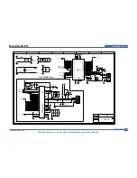
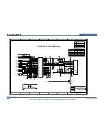
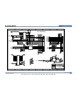

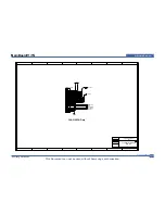
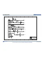
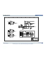
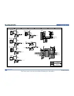
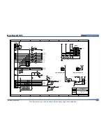
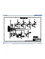


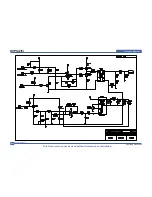

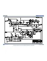
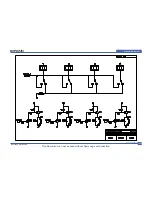


Schematic Diagram
Service Manual
11-20
This Document can not be used without Samsung’s authorization.
Samsung Electronics
A
A
B
B
C
C
D
D
1
1
2
2
3
3
4
4
Title
Size
No.
Rev.
File
Date
Time
of
Top Circuit
A3
.docno.
.rev.
C:\...\
\TYPE III-V2_050602.sch
2005/06/02
19:47
1
1
note1
note2
note3
note4
note5
R51
1W50m
TNR01
10D561
F01
250V8A
LF01
CV505110B
CON1
C01
224
R52
R53
91JX2_2012
0
0
0
0
PC51
TLP3061F
C52
104K_2012
C51
630V333k
AR02
1KV
Q51
600V16A
C04
104
R010
1W22(mini)
D01
1KV1A-CHIP
BD01
600V6A
TH01
10D9
Q01
600V12A
R04
1K_2012
C11
450V220uF
R12
R13
R11
200KX3_3216
R15
R16
R14
91KX3_3216
C12
630V333K
Q11
600V4A
Q12
600V11A
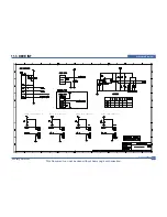
DEMAG
1
FB
2
GND
4
CS
3
OUT
5
VCC
6
NC
7
VI
8
U11
IC_1207A-CHIP
R20
10K_2012
R21
100_2012
R19
100_2012
D12
MMSD4148
R18
10_2012
R23
47_3216
R24
100K_2012
C16
20p_2012
C14
100n_2012
C15
35V47uF
D11
1KV1A-CHIP
R22
5W0.25
C13
1n_2012
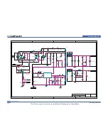
D103
D105
200V20AX2
D104
60V20A
C72
1KV103K
C73
1KV103K
C75
35V1000uFX2
C71
C18
AD102
TNR11
7D221
ZD71
20V-CHIP
L71
5uH
R92
1K_2012
C91
225_2012
R93
1KF_2012
R94
1KF_2012
R76
470_2012
C77
35V470uF
R77
3W120
Q71
2222A-CHIP
C78
50V104(mono)
F71
250V5A
ZD11
20V-CHIP
R75
200_2012
C76
16V1000uF
PC11-1
817B
C74
16V1000uF
U91
431-CHIP
C17
AD102
AR03
1KV
AR01
600V
AR04
600V
C05
104K_2012
R59
22_2012
R17
100_2012
L01
F02
250V5A
LF002
CV930160P
R55
1/2W180(MINI)
L51
R54
1W50m
R02
R03
C02
AD102
C03
AD102
R01
200K_3216X3
ZD12
20V-CHIP
R91
220_2012
PC11-2
817B
R57
1K_2012
Q52
2222A-CHIP
R56
1W1.5KJ(mini)
R58
4.7K_2012
CON2-1
CON2-2
CON3-11,13,15
HEATSINK
CON3-3,5,7,9
CON3-4,6,8,10
CON3-12,14,16
CON3-2
CON3-1
T1
8
24V 4.4A
GND
5V 3A
GND
Fuser Count
24VS
11.6 SMPS-220V
Summary of Contents for CLP-300
Page 14: ...Product Specifications Samsung Electronics Service Manual 2 3 2 2 2 Controller S W ...
Page 15: ...Samsung Electronics Service Manual Product Specifications 2 4 2 2 3 Paper Handling ...
Page 18: ...Product Specifications Samsung Electronics Service Manual 2 7 2 3 Model Comparison Table ...
Page 29: ...System Overview Samsung Electronics Service Manual 3 11 CHORUSm Internal Block Diagram ...
Page 45: ...Samsung Electronics Service Manual S W Structure and Descriptions 4 6 4 11 Initailize Flow ...
Page 46: ...S W Structure and Descriptions Samsung Electronics Service Manual 4 7 ...
Page 53: ...Disassembly and Reassembly Samsung Electronics Service Manual 5 7 ...
Page 54: ...Samsung Electronics Service Manual Disassembly and Reassembly 5 8 ...
Page 55: ...Disassembly and Reassembly Samsung Electronics Service Manual 5 9 ...
Page 70: ...Samsung Electronics Service Manual Alignment and Adjustmens 6 10 ...
Page 71: ...Samsung Electronics Alignment and Adjustmens Samsung Electronics Service Manual 6 11 ...
Page 83: ...Samsung Electronics Service Manual Troubleshooting 7 4 ...
Page 84: ...Troubleshooting Samsung Electronics Service Manual 7 5 ...
Page 85: ...Samsung Electronics Service Manual Troubleshooting 7 6 ...
Page 96: ...Troubleshooting Samsung Electronics Service Manual 7 17 7 8 5 Background 7 8 6 JAM 0 ...
Page 104: ...8 4 Front Cover 0 2 1 Samsung Electronics Service Manual 8 5 Exploded Views Parts List ...
Page 160: ...www s manuals com ...


