background image

11

Working with the D2500 Faders

Unlike menu driven, black box devices, the D2500 is a digi-
tal equalizer with standard 45 mm analog faders for the 
31 filter bands, plus the Master level fader for true analog 
control.  If you are operating the D2500 in Manual mode, 
the faders work exactly like you would expect on a stan-
dard analog graphic equalizer.  However, since the D2500 
is able to recall and save EQ curves in its internal memory, 
the physical fader for any, or all of the EQ filter bands, 
may not be in the same positions as they were when they 
were saved into the memory preset.  This means that the 
hardware faders can be at a different physical position, 
compared to the actual setting for the filter band that’s 
in memory. The D2500 offers an easy to use system for 
matching, or nulling out, the EQ faders to the memory 
positions using the above and below fader Null, or match-
ing LED’s.

Note:

The null point is the exact location where the  fader's 

TT

physical postion matches the level of the digital filter.

physical

physical

The D2500 lets you match, or null, the fader to the memo-
ry location by using two Null LED’s, one red, placed above 
the fader, and green, placed below the fader. The follow-
ing example shows you how to work the faders with their 
associated over and under matching, or Null LED when 
loading a preset.  

Note: In this exersise you will be loading in preset 00. If you 
are not very familiar with working with the presets, just stay 
on preset 00.  Preset 00 can not be overwritten, so don't worry 
about erasing anything.

•  Press the MANUAL button to deselect MANUAL mode 
(LED OFF).

•  Set all the faders to their center detent position.

•  Press the LOAD switch.

•   Now, use the Data Wheel to dial up preset 00.  Pre set 00 

contains a default setting with all faders set to zero.

•   Next, press load again. Now you have loaded in preset 

00. 

At this point all the EQ faders will be lit, except the one 
assigned to the LCD, and none of the over and under Null 
LED’s should be lit.

•   Now, push several of the faders up and down to random 

positions.

•  Press the LOAD switch.

•   Now, use the Data Wheel to dial up preset 00.  Pre set 00 

contains a default setting with all faders set to zero.

Operating the D2500  

At this point you should notice that the red and green, null 
LED’s are now lit above and below the faders that have 
been moved.  This LED indication is telling you that the 
EQ faders need to be moved if you want to null, or match, 
them to the original saved positions. 

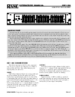
•   Choose an EQ fader that has the red Null LED lit and 

push the fader up slowly until the red Null LED goes off.  
Now the physical hardware EQ fader is set to the same 
position as the EQ filter band in memory.

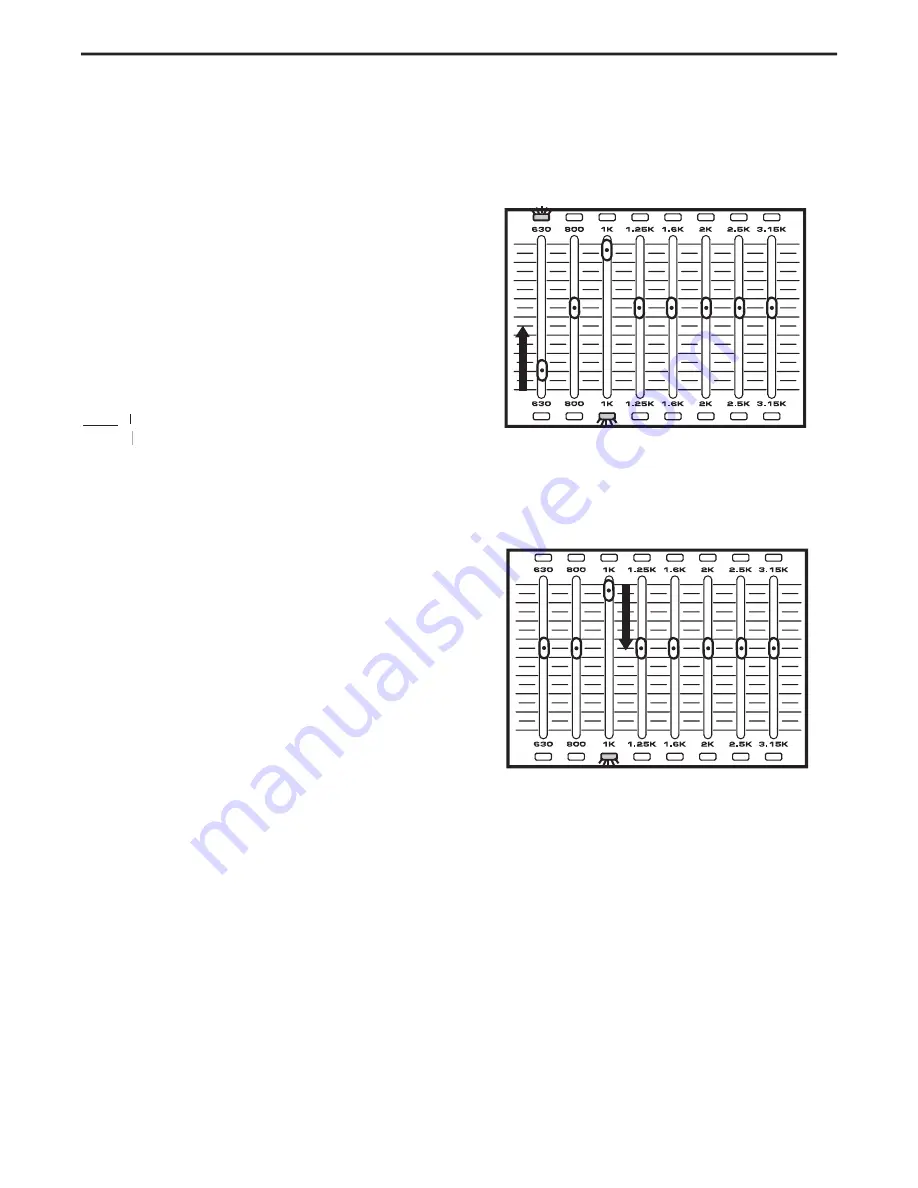
•   Choose an EQ fader that has the green Null LED lit and 

push the fader down slowly until the green Null LED 
goes off.  Now the physical hardware EQ fader is set to 
the same position as the EQ filter band in memory.

•  Press all the EQ faders to the center, zero mark.

•  Press the LOAD switch.

•  Use the Daawheel to dial up preset 00.

•  Press the LOAD switch to reload presset 00.

Summary of Contents for D-2500

Page 1: ...DIGITAL DUAL 31 BAND EQUALIZATION SYSTEM...

Page 2: ...r objects have fallen into the unit the unit has been exposed to rain or moisture does not operate normally or has been dropped PRECAUCION Para reducir el riesgo de incendios o descargas no permita qu...

Page 3: ...D2500 Faders 11 Using the Process Switches 12 Using the EQ section 12 Using the FEEDBACK Management Function 12 Using the Internal Noise GATE 13 Using the Internal DELAY 13 Setting up and Using the Hi...

Page 4: ...n 99 pre set locations Using the large easy to read LCD display and conve nient data wheel it s possible to save your favorite equalization curves and recall them in the future Or when using the D2500...

Page 5: ...and suppression Manual or Auto mode with Automated Filter Restoration The D2500 s fader can be set for either 3 6 or 12 dB of gain and attenuation for each of the frequency bands An onboard programmab...

Page 6: ...alizer to the physical controls 10 LINK switch Used to control the left and right CH1 and CH2 equalizer simultaneously with the one set of physi cal controls Controls and Functions Front Panel Layout...

Page 7: ...Electronically balanced XLR jack output 19 LIMITER switch This switch is used to page through the LIMITER parameters When selected the amber LED will illuminate and the LIMITER parameters will be disp...

Page 8: ...NG UP THE D2500 to work in MANUAL mode The D2500 is simple to use In fact you can use it just like a standard analog graphic equalizer by simply set ting the unit to MANUAL mode Setting up your D2500...

Page 9: ...lizer D2500 Quick Start 7 12 Apply an input signal to the D2500 if sending signal from a mixer output bus drive the mixer s output meters at approximately 0 VU While the input signal is present slowly...

Page 10: ...The D2500 function switch sections are arranged on the front panel as follows First is the BYPASS switch that enables you to turn the equalizer and all effects on or off Next is the A B switch that l...

Page 11: ...dwidth for either 1 4 1 3 1 2 of an octave or to AUTO which will allow each of the 31 filters to be set to an individual bandwidth calculated by the onboard DSP To access the Filter band width setting...

Page 12: ...and control either one or both sides The state of these switches will determine which of the left and right signals are affected by the hardware control surface Using the LINK switch If you want to s...

Page 13: ...loading in preset 00 If you are not very familiar with working with the presets just stay on preset 00 Preset 00 can not be overwritten so don t worry about erasing anything Press the MANUAL button to...

Page 14: ...zer filters as well as the Master Fader filters are displayed in the LCD window You can use the Data Wheel to scroll through the frequencies and display the filter levels in the main LCD window It is...

Page 15: ...al rises above the Threshold level The Noise Gate Switch Has Two Clicks Click Menu Function Value 1 Gate Rel Release Time 50 100 2 Gate Th Threshold Level 0 100 dB To operate the D2500 digital noise G...

Page 16: ...your system When equal izing a monitor system you may use both the HP and LP filters to roll off the high and lows for a vocal eq contour Any good high and low pass filter will allow you to choose the...

Page 17: ...set from 50 to 100 which is the equivalent to 2 to 15 seconds Using the A B Feature The A B switch lets you compare the actual modified program to the last program recalled or stored in memory After...

Page 18: ...tion go on to the next step If you want to choose a new memory location use the Data Wheel to scroll through the 99 preset num bers until you reach the number you want to recall into memory Once you s...

Page 19: ...hese modes and their associated parameters Setting the D2500 to Transmit and Receive MIDI To enable the D2500 to send and receive MIDI data follow these steps Press the MIDI switch until that LCD read...

Page 20: ...l to select SysEx T R Use the Data Wheel to select SysEx OFF and the D2500 will not transmit or receive any system exclusive mes sages To keep the new changes press the STORE button and you will exit...

Page 21: ...e or for any EQ response curve that you may have saved in memory THIS DEVICE COMPLIES WITH PART 15 OF THE FCC RULES CLASS B OPERATION IS SUBJECT TO THE FOLLOWING TWO CONDITIONS 1 THIS DEVICE MUST NOT...

Page 22: ...ORE NOTE You may need to come back to this to make the final mic gain adjustment once you start generating the PINK NOISE at the desired operating level AUTO EQ YOUR SYSTEM Once you have the Mic Input...

Page 23: ...reads F R Now turn the Data Wheel until the dispay reads 12 dB Press the D2500 s Global switch a few times until the display reads F Bw Then turn the Data Wheel until the display reads 1 3 Oct Press...

Page 24: ...ting the D2500 with the D1500 RTA Press RES and use the Data Wheel to select 2 0 dB which will correspond to the D2500 provided that the Frequency Range Global Menu of the D2500 is set to the default...

Page 25: ...wise until the LED indicators are oper ating in a range approximately halfway up the display Operating the D2500 with the D1500 RTA Operating the D2500 with the D1500 RTA Using the signal Generator Th...

Page 26: ...outputs are connected to the inputs of each active self powered loudspeaker Using the D2500 with Passive Speakers In this example the mixer s stereo output is connected to the D2500 s inputs Then the...

Page 27: ...n D2500 is used for both the main PA speakers running a mono mix and for the monitor mix also in mono For the main PA the mixer s MONO output is connected to the D2500 s Channel 1 input Then the D2500...

Page 28: ...peakers Then the outputs are connected to the inputs of the power amplifier connected to passive loudspeakers For the monitor mix the mixer s AUX1 output is connected to the second D2500 s channel 1 i...

Page 29: ...g set up Follow the cable diagrams below for connecting your monitor system 27 XLR Insert Cable Balanced 1 4 to FEMALE XLR Cable Unbalanced XLR to 1 4 Cable Balanced MALE XLR to 1 4 Cable Unbalanced M...

Page 30: ...p 4 dBu 1 kHz unity gain Digital Processing Converter 24 bit Delta Sigma 64 128 oversampling Sample rate AIO1 AIO2 32 44 1 48 64 88 2 96 kHz DIO1 96 kHzType digital 31 band equalizer DIO1 96 kHzType d...

Page 31: ......

Page 32: ...Samson Technologies Corp 575 Underhill Blvd P O Box 9031 Syosset NY 11791 9031 Phone 1 800 3 SAMSON 1 800 372 6766 Fax 516 364 3888 www samsontech com...

Reviews: