5-6
EB 9510 EN
Installation
5.4 Mounting the SAM Connect
Gateway
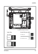
The following options to mount the gateway
in the plant are available:
−
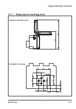
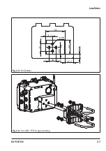
4x M8 tapped holes on the back (see
Fig. 5-3 for hole pattern)
−
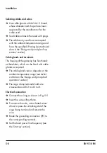
Kit for pipe mounting as accessory (see
Additional points that apply concerning in
-
stallation:
Î
Observe mounting position.
Î
Mount the device free of vibration.
Î
Use mounting part with clamp for pipe
mounting to attach it to a vertical or hori-
zontal pipe.
5.5
Establishing electrical
connections
Risk of fatal injury due to electric shock
(230 V version).
Î
Before connecting wiring, performing
any work on the device or opening the
device, disconnect the voltage supply
and protect it against unintentional re
-
connection.
Î
Only use power interruption devices that
are protected against unintentional re
-
connection of the power supply.
Î
Upon installation of the electric cables,
you are required to observe the regula
-
tions concerning low-voltage installations
according to DIN VDE 0100 as well as
the regulations of your local power sup
-
plier.
Î
Use a suitable voltage supply which
guarantees that no dangerous voltages
reach the device in normal operation or
in the event of a fault in the system or
any other system parts.
Risk of damage to the electronics due to the
incorrect connection of the electrical power
supply.
Î
Observe the permissible tolerances of the
supply voltage.
Î
For wiring, you are required to observe
the relevant regulations concerning de
-
vice safety and electromagnetic compati
-
bility.
DANGER
!
NOTICE
!
Summary of Contents for 5007-2 Series
Page 8: ...1 4 EB 9511 EN...
Page 12: ...2 4 EB 9511 EN...
Page 24: ...3 12 EB 9511 EN...
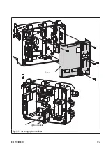
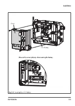
Page 29: ...EB 9510 EN 5 3 Cover Option module Fig 5 1 Inserting option modules...
Page 36: ...5 10 EB 9510 EN...
Page 50: ...11 2 EB 9511 EN...
Page 52: ...12 2 EB 9511 EN...
Page 54: ...13 2 EB 9511 EN...
Page 56: ...14 2 EB 9511 EN...
Page 68: ...17 2 EB 9511 EN...
Page 69: ......
Page 70: ...4 EB 9511 EN...
Page 71: ...EB 9511 EN 5...

