5-8
EB 9510 EN
Installation
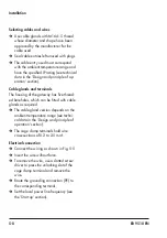
Selecting cables and wires
Î
Use cable glands with M16x1.5 thread
whose diameter and shape have been
approved by the manufacturer for the
cable used.
Î
Seal cable entries left unused with plugs.
Î
The cable entry used must correspond
with the ambient temperature range and
have the specified IP rating (see technical
data in the 'Design and principle of op-
eration' section).
Cable glands and terminals
The housing of the gateway has five thread
-
ed boreholes, which can be fitted with cable
glands as required.
Î
The cable gland version depends on the
ambient temperature range (see techni-
cal data in the 'Design and principle of
operation' section).
Î
The cage clamp terminals hold wire
cross-sections of 0.2 to 2.5 mm².
Electrical connection
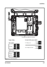
Î
Connect the wiring as shown in Fig. 5-5.
Î
Insert the wire without force.
Î
To remove the wire, use a slotted screw-
driver to press the unlocking slot of the
cage clamp terminal and remove the
wire.
Î
Route the grounding connection (PE) to
the corresponding terminal.
Î
Set the local power line frequency (see
the 'Start-up' section).
Summary of Contents for 5007-2 Series
Page 8: ...1 4 EB 9511 EN...
Page 12: ...2 4 EB 9511 EN...
Page 24: ...3 12 EB 9511 EN...
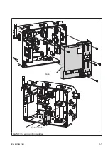
Page 29: ...EB 9510 EN 5 3 Cover Option module Fig 5 1 Inserting option modules...
Page 36: ...5 10 EB 9510 EN...
Page 50: ...11 2 EB 9511 EN...
Page 52: ...12 2 EB 9511 EN...
Page 54: ...13 2 EB 9511 EN...
Page 56: ...14 2 EB 9511 EN...
Page 68: ...17 2 EB 9511 EN...
Page 69: ......
Page 70: ...4 EB 9511 EN...
Page 71: ...EB 9511 EN 5...

