18 | SAMLEX AMErICA INC.
Check the individual cell voltages / specific gravity. If the inter-cell voltage difference is more
than a 0.2V, or the specific gravity difference is 0.015 or more, the cells will require equalization.
Please note that only non-sealed / vented / flooded / wet cell batteries are equalized.
Do not equalize sealed / VRLA type of AGM or Gel Cell Batteries.
1.4.9 State of Discharge of a Loaded battery – Low battery / DC input Voltage
Alarm and Shutdown in inverters
Most inverter hardware estimate the State of Discharge of the loaded battery by measuring
the voltage at the inverter’s DC input terminals (considering that the DC input cables are thick
enough to allow a negligible voltage drop between the battery and the inverter).
Inverters are provided with a buzzer alarm to warn that the loaded battery has been deeply
discharged to around 80% of the rated capacity.
Normally, the buzzer alarm is triggered
when the voltage at the DC input terminals of the inverter has dropped to around
10.5V for a 12V battery or 21V for 24V battery at C-Rate discharge current of C/5
Amps and electrolyte temp. of 80°F.
The inverter is shut down if the terminal voltage at C/5
discharge current falls further to 10V for 12V battery or 20V for 24V battery.
The State of Discharge of a battery is estimated based on the measured terminal voltage of the
battery. The terminal voltage of the battery is dependent upon the following:
-
temperature of the battery electrolyte:
Temperature of the electrolyte affects the electrochemical
reactions inside the battery and produces a Negative Voltage Coefficient – during charging /
discharging, the terminal voltage drops with rise in temperature and rises with drop in temperature
-
the amount of discharging current or “C-rate”:
A battery has non linear internal resistance
and hence, as the discharge current increases, the battery terminal voltage decreases non-linearly
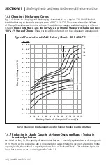
The discharge curves in fig. 1.4 show the % State of Charge versus the terminal voltage of
typical flooded Lead Acid battery under different charge /discharge currents, i.e. “C-rates”
and fixed temperature of 80°f.
(Please note that the X-Axis of the curves shows the % of
State of Charge. the % of State of Discharge will be 100% - % State of Charge).
1.4.10 Low DC input Voltage Alarm in inverters
As stated earlier, the buzzer alarm is triggered when the voltage at the DC input terminals of
the inverter has dropped to around 10.5V for a 12V battery or 21V for 24V battery at C-rate
discharge current of C/5 Amps. Please note that the terminal voltage relative to a particular State
of Discharge decreases with the rise in the value of the discharge current. for example, terminal
voltages for a State of Discharge of 80% (State of Charge of 20%) for various discharge currents
will be as given at Table 1.11 (refer to fig. 1.4 for parameters and values shown in Table 1.11):
table 1.11 terMinAL VoLtAge AnD SoC oF LoADeD bAttery
Discharge
Current:
C-rate
terminal Voltage at 80% State
of Discharge (20% SoC)
terminal Voltage when Completely
Discharged (0% SoC)
12V
24V
12V
24V
C/3 A
10.45V
20.9V
09.50V
19.0V
C/5 A
10.90V
21.8V
10.30V
20.6V
C/10 A
11.95V
23.9V
11.00V
22.0V
C/20 A
11.85V
23.7V
11.50V
23.0V
C/100 A
12.15V
24.3V
11.75V
23.5V
SECTIOn 1 |
Safety Instructions & general Information


